
Analog television is the original television technology that uses analog signals to transmit video and audio. In an analog television broadcast, the brightness, colors and sound are represented by amplitude, phase and frequency of an analog signal.
The amplitude of a periodic variable is a measure of its change in a single period. The amplitude of a non-periodic signal is its magnitude compared with a reference value. There are various definitions of amplitude, which are all functions of the magnitude of the differences between the variable's extreme values. In older texts, the phase of a periodic function is sometimes called the amplitude.
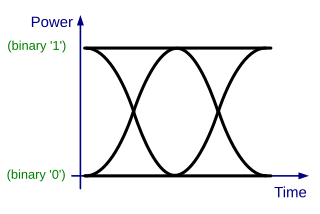
In telecommunications, an eye pattern, also known as an eye diagram, is an oscilloscope display in which a digital signal from a receiver is repetitively sampled and applied to the vertical input (y-axis), while the data rate is used to trigger the horizontal sweep (x-axis). It is so called because, for several types of coding, the pattern looks like a series of eyes between a pair of rails. It is a tool for the evaluation of the combined effects of channel noise, dispersion and intersymbol interference on the performance of a baseband pulse-transmission system. The technique was first used with the WWII SIGSALY secure speech transmission system.
In electronics, fall time is the time taken for the amplitude of a pulse to decrease (fall) from a specified value to another specified value.
In telecommunications and data storage, Manchester code is a line code in which the encoding of each data bit is either low then high, or high then low, for equal time. It is a self-clocking signal with no DC component. Consequently, electrical connections using a Manchester code are easily galvanically isolated.
In radio communication, multipath is the propagation phenomenon that results in radio signals reaching the receiving antenna by two or more paths. Causes of multipath include atmospheric ducting, ionospheric reflection and refraction, and reflection from water bodies and terrestrial objects such as mountains and buildings. When the same signal is received over more than one path, it can create interference and phase shifting of the signal. Destructive interference causes fading; this may cause a radio signal to become too weak in certain areas to be received adequately. For this reason, this effect is also known as multipath interference or multipath distortion.
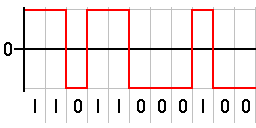
In telecommunications, a non-return-to-zero (NRZ) line code is a binary code in which ones are represented by one significant condition, usually a positive voltage, while zeros are represented by some other significant condition, usually a negative voltage, with no other neutral or rest condition.
A passband is the range of frequencies or wavelengths that can pass through a filter. For example, a radio receiver contains a bandpass filter to select the frequency of the desired radio signal out of all the radio waves picked up by its antenna. The passband of a receiver is the range of frequencies it can receive when it is tuned into the desired frequency (channel).
In telecommunications, attack-time delay is the time needed for a receiver or transmitter to respond to an incoming signal.

A square wave is a non-sinusoidal periodic waveform in which the amplitude alternates at a steady frequency between fixed minimum and maximum values, with the same duration at minimum and maximum. In an ideal square wave, the transitions between minimum and maximum are instantaneous.
In a digitally modulated signal or a line code, symbol rate, modulation rate or baud rate is the number of symbol changes, waveform changes, or signaling events across the transmission medium per unit of time. The symbol rate is measured in baud (Bd) or symbols per second. In the case of a line code, the symbol rate is the pulse rate in pulses per second. Each symbol can represent or convey one or several bits of data. The symbol rate is related to the gross bit rate, expressed in bits per second.

A wind profiler is a type of weather observing equipment that uses radar or sound waves (SODAR) to detect the wind speed and direction at various elevations above the ground. Readings are made at each kilometer above sea level, up to the extent of the troposphere. Above this level there is inadequate water vapor present to produce a radar "bounce." The data synthesized from wind direction and speed is very useful to meteorological forecasting and timely reporting for flight planning. A twelve-hour history of data is available through NOAA websites.
A radar system uses a radio-frequency electromagnetic signal reflected from a target to determine information about that target. In any radar system, the signal transmitted and received will exhibit many of the characteristics described below.
In telecommunication, the term gating has the following meanings:
- The process of selecting only those portions of a wave between specified time intervals or between specified amplitude limits.
- The controlling of signals by means of combinational logic elements.
- A process in which a predetermined set of conditions, when established, permits a second process to occur.

A digital signal is a signal that represents data as a sequence of discrete values; at any given time it can only take on, at most, one of a finite number of values. This contrasts with an analog signal, which represents continuous values; at any given time it represents a real number within a continuous range of values.
Pulse-Doppler signal processing is a radar and CEUS performance enhancement strategy that allows small high-speed objects to be detected in close proximity to large slow moving objects. Detection improvements on the order of 1,000,000:1 are common. Small fast moving objects can be identified close to terrain, near the sea surface, and inside storms.
The spectrum of a chirp pulse describes its characteristics in terms of its frequency components. This frequency-domain representation is an alternative to the more familiar time-domain waveform, and the two versions are mathematically related by the Fourier transform. The spectrum is of particular interest when pulses are subject to signal processing. For example, when a chirp pulse is compressed by its matched filter, the resulting waveform contains not only a main narrow pulse but, also, a variety of unwanted artifacts many of which are directly attributable to features in the chirp's spectral characteristics.
The chirp pulse compression process transforms a long duration frequency-coded pulse into a narrow pulse of greatly increased amplitude. It is a technique used in radar and sonar systems because it is a method whereby a narrow pulse with high peak power can be derived from a long duration pulse with low peak power. Furthermore, the process offers good range resolution because the half-power beam width of the compressed pulse is consistent with the system bandwidth.

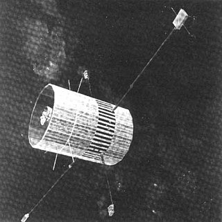
Explorer 43, also called IMP-I and IMP-6, was a NASA satellite launched as part of the Explorers program. Explorer 43 was launched on 13 March 1971 from Cape Canaveral Air Force Station (CCAFS) with a Thor-Delta M6 launch vehicle. Explorer 43 was the sixth satellite of the Interplanetary Monitoring Platform.
Explorer 47, was a NASA satellite launched as part of the Explorers program. Explorer 47 was launched on 23 September 1972 from Cape Canaveral, Florida, with a Thor-Delta 1604. Explorer 47 was the ninth overall launch of the Interplanetary Monitoring Platform series, but received the launch designation "IMP-7" because two previous "Anchored IMP" flights had used "AIMP" instead.

