Related Research Articles

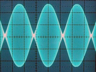
Amplitude modulation (AM) is a modulation technique used in electronic communication, most commonly for transmitting messages with a radio wave. In amplitude modulation, the amplitude of the wave is varied in proportion to that of the message signal, such as an audio signal. This technique contrasts with angle modulation, in which either the frequency of the carrier wave is varied, as in frequency modulation, or its phase, as in phase modulation.
In electronics, the figures of merit of an amplifier are numerical measures that characterize its properties and performance. Figures of merit can be given as a list of specifications that include properties such as gain, bandwidth, noise and linearity, among others listed in this article. Figures of merit are important for determining the suitability of a particular amplifier for an intended use.

An amplifier, electronic amplifier or (informally) amp is an electronic device that can increase the magnitude of a signal. It is a two-port electronic circuit that uses electric power from a power supply to increase the amplitude of a signal applied to its input terminals, producing a proportionally greater amplitude signal at its output. The amount of amplification provided by an amplifier is measured by its gain: the ratio of output voltage, current, or power to input. An amplifier is defined as a circuit that has a power gain greater than one.

Electromagnetic compatibility (EMC) is the ability of electrical equipment and systems to function acceptably in their electromagnetic environment, by limiting the unintentional generation, propagation and reception of electromagnetic energy which may cause unwanted effects such as electromagnetic interference (EMI) or even physical damage to operational equipment. The goal of EMC is the correct operation of different equipment in a common electromagnetic environment. It is also the name given to the associated branch of electrical engineering.
The optical power budget in a fiber-optic communication link is the allocation of available optical power among various loss-producing mechanisms such as launch coupling loss, fiber attenuation, splice losses, and connector losses, in order to ensure that adequate signal strength is available at the receiver. In optical power budget attenuation is specified in decibel (dB) and optical power in dBm.
In an optical communications link, the optical power margin is the difference between the optical power that is launched by a given transmitter into the fiber, less transmission losses from all causes, and the minimum optical power that is required by the receiver for a specified level of performance. An optical power margin is typically measured using a calibrated light source and an optical power meter.

In radio transmission, transmitter power output (TPO) is the actual amount of power of radio frequency (RF) energy that a transmitter produces at its output.
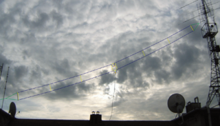
The Tilted Terminated Folded Dipole or Balanced Termination, Folded Dipole (BTFD) - also known as W3HH antenna - is a general-purpose shortwave antenna developed in the late 1940s by the United States Navy. It performs reasonably well over a broad frequency range, without marked dead spots in terms of either frequency, direction, or angle of radiation above the horizon.

An antenna analyzer or in British aerial analyser is a device used for measuring the input impedance of antenna systems in radio electronics applications.
A link budget is an accounting of all of the power gains and losses that a communication signal experiences in a telecommunication system; from a transmitter, through a communication medium such as radio waves, cable, waveguide, or optical fiber, to the receiver. It is an equation giving the received power from the transmitter power, after the attenuation of the transmitted signal due to propagation, as well as the antenna gains and feedline and other losses, and amplification of the signal in the receiver or any repeaters it passes through. A link budget is a design aid, calculated during the design of a communication system to determine the received power, to ensure that the information is received intelligibly with an adequate signal-to-noise ratio. Randomly varying channel gains such as fading are taken into account by adding some margin depending on the anticipated severity of its effects. The amount of margin required can be reduced by the use of mitigating techniques such as antenna diversity or multiple-input and multiple-output (MIMO).
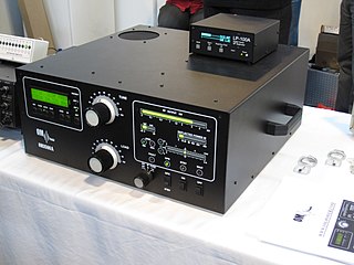
A linear amplifier is an electronic circuit whose output is proportional to its input, but capable of delivering more power into a load. The term usually refers to a type of radio-frequency (RF) power amplifier, some of which have output power measured in kilowatts, and are used in amateur radio. Other types of linear amplifier are used in audio and laboratory equipment. Linearity refers to the ability of the amplifier to produce signals that are accurate copies of the input. A linear amplifier responds to different frequency components independently, and tends not to generate harmonic distortion or intermodulation distortion. No amplifier can provide perfect linearity however, because the amplifying devices—transistors or vacuum tubes—follow nonlinear transfer function and rely on circuitry techniques to reduce those effects. There are a number of amplifier classes providing various trade-offs between implementation cost, efficiency, and signal accuracy.
A radio transmitter or just transmitter is an electronic device which produces radio waves with an antenna. Radio waves are electromagnetic waves with frequencies between about 30 Hz and 300 GHz. The transmitter itself generates a radio frequency alternating current, which is applied to the antenna. When excited by this alternating current, the antenna radiates radio waves. Transmitters are necessary parts of all systems that use radio: radio and television broadcasting, cell phones, wireless networks, radar, two way radios like walkie talkies, radio navigation systems like GPS, remote entry systems, among numerous other uses.
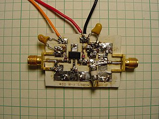
A radio-frequency power amplifier is a type of electronic amplifier that converts a low-power radio-frequency (RF) signal into a higher-power signal. Typically, RF power amplifiers are used in the final stage of a radio transmitter, their output driving the antenna. Design goals often include gain, power output, bandwidth, power efficiency, linearity, input and output impedance matching, and heat dissipation.
A valve RF amplifier or tube amplifier (U.S.) is a device for electrically amplifying the power of an electrical radio frequency signal.

Radio-frequency (RF) engineering is a subset of electrical engineering involving the application of transmission line, waveguide, antenna, radar, and electromagnetic field principles to the design and application of devices that produce or use signals within the radio band, the frequency range of about 20 kHz up to 300 GHz.
IEEE 802.15.4a was an amendment to IEEE 802.15.4-2006 specifying that additional physical layers (PHYs) be added to the original standard. It has been merged into and is superseded by IEEE 802.15.4-2011.
In broadcasting, a transposer or translator is a device in or beyond the service area of a radio or television station transmitter that rebroadcasts signals to receivers which can’t properly receive the signals of the transmitter because of a physical obstruction. A translator receives the signals of the transmitter and rebroadcasts the signals to the area of poor reception. Sometimes the translator is also called a relay transmitter, rebroadcast transmitter or transposer. Since translators are used to cover a small shadowed area, their output powers are usually lower than that of the radio or television station transmitters feeding them.
Split sound is an old system in analog television transmitters. It has long been superseded, but transmitters working on this principle are still in use. In this system there are two almost independent transmitters, one for sound (aural) and one for picture (visual). The system requires more energy input relative to broadcast energy than the alternative system known as intercarrier system.

An RF module is a (usually) small electronic device used to transmit and/or receive radio signals between two devices. In an embedded system it is often desirable to communicate with another device wirelessly. This wireless communication may be accomplished through optical communication or through radio-frequency (RF) communication. For many applications, the medium of choice is RF since it does not require line of sight. RF communications incorporate a transmitter and a receiver. They are of various types and ranges. Some can transmit up to 500 feet. RF modules are typically fabricated using RF CMOS technology.

The 7-16 DIN connector or 7/16 is a 50 Ω threaded RF connector used to join coaxial cables. It was designed to reduce passive intermodulation from multiple transmitters. It is among the most widely used high power RF connectors in cellular network antenna systems. Originally popular in Europe, it has gained widespread use in the US and elsewhere.
References
 This article incorporates public domain material from Federal Standard 1037C. General Services Administration. Archived from the original on 2022-01-22. (in support of MIL-STD-188).
| | This article related to radio communications is a stub. You can help Wikipedia by expanding it. |