An RF switch or microwave switch is a device to route high frequency signals through transmission paths. RF (radio frequency) and microwave switches are used extensively in microwave test systems for signal routing between instruments and devices under test (DUT). Incorporating a switch into a switch matrix system enables you to route signals from multiple instruments to single or multiple DUTs. This allows multiple tests to be performed with the same setup, eliminating the need for frequent connects and disconnects. The entire testing process can be automated, increasing the throughput in high-volume production environments.
Like other electrical switches, RF and microwave switches provide different configurations for many different applications. Below is a list of typical switch configurations and usage:
Bypass switches insert or remove a test component from a signal path.
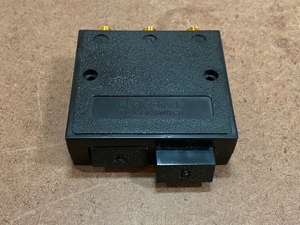
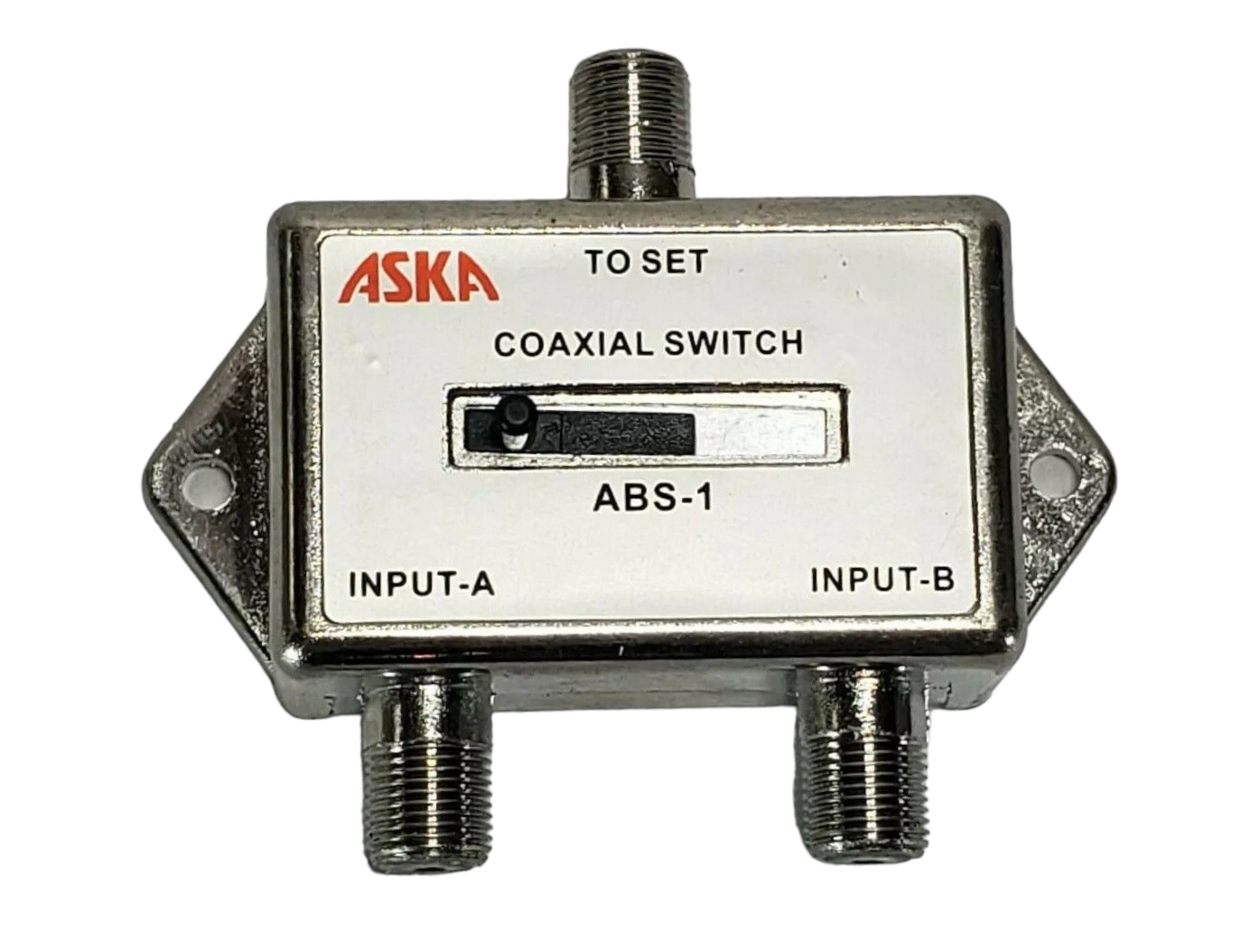
RF A/B switches are designed to switch between a cable company CATV signal and an Off-Air antenna signal or other home video products with coaxial cable RF connections.[1]
RF A/B switches come in button[2] or sliding switches.[3]
Some of the electromechanical switches from Agilent Technologies
A solid state switch is an electronic switching device based on semiconductor technology (e.g. MOSFET, PIN diode). It functions similarly to an electromechanical switch except that it has no moving parts. Some of the solid state switches from Agilent Technologies
Parameters
Electromechanical
Solid state
Frequency range
from [DC]
from kHz
Insertion loss
low
high
Return loss
good
good
Repeatability
good
excellent
Isolation
excellent
good
Switching speed
in ms
in ns
Settling time
< 15 ms
< 1 μs
Power handling
high
low
Video leakage
none
low
Operating life
5 million cycles
infinite
ESD immunity
high
low
Sensitive to
vibration
RF power overstress
Parameters
Frequency range
RF and microwave applications range in frequency from 100MHz for semiconductor to 60GHz for satellite communications. Broadband accessories increase test system flexibility by extending frequency coverage. However, frequency is always application dependent and a broad operating frequency may be sacrificed to meet other critical parameters. For example, a network analyzer may perform a 1 ms sweep for an insertion loss measurement, so for this application settling time or switching speed becomes the critical parameter for ensuring measurement accuracy.
Insertion loss
In addition to proper frequency selection, insertion loss is critical to testing. Losses greater than 1 or 2dB will attenuate peak signal levels and increase rising and falling edge times. A low insertion loss system can be achieved by minimizing the number of connectors and through-paths, or by selecting low insertion loss devices for system configuration. As power is expensive at higher frequencies, electromechanical switches provide the lowest possible loss along the transmission path.
Return loss
Return loss is caused by impedance mismatch between circuits. At microwave frequencies, the material properties as well as the dimensions of a network element play a significant role in determining the impedance match or mismatch caused by the distributed effect. Switches with excellent return loss performance ensure optimum power transfer through the switch and the entire network.
Repeatability
Low insertion loss repeatability reduces sources of random errors in the measurement path, which improves measurement accuracy. The repeatability and reliability of a switch guarantees measurement accuracy and can cut the cost of ownership by reducing calibration cycles and increasing test system uptime.
Isolation
Isolation is the degree of attenuation from an unwanted signal detected at the port of interest. Isolation becomes more important at higher frequencies. High isolation reduces the influence of signals from other channels, sustains the integrity of the measured signal, and reduces system measurement uncertainties. For instance, an RF switch matrix may need to route a signal to a spectrum analyzer for measurement at –70 dBm and to simultaneously route another signal at +20 dBm. In this case, switches with high isolation, 90dB or more, will keep the measurement integrity of the low-power signal.
Switching speed
Switching speed is defined as the time needed to change the state of a switch port (arm) from "ON' to "OFF" or from "OFF" to "ON".
Settling time
As switching time only specifies an end value of 90% of the settled/final value of the RF signal, settling time is often highlighted in solid state switch performance where the need for accuracy and precision is more critical. Settling time is measured to a level closer to the final value. The widely used margin-to-final value of settling time is 0.01dB (99.77% of the final value) and 0.05dB (98.86% of the final value). This specification is commonly used for GaAsFET switches because they have a gate lag effect caused by electrons becoming trapped on the surface of the GaAs.
Power handling
Power handling defines the ability of a switch to handle power and is very dependent on the design and materials used. There are different power handling ratings for switches such as hot switching, cold switching, average power and peak power. Hot switching occurs when RF/microwave power is present at the ports of the switching at the time of the switching. Cold switching occurs when the signal power is removed before switching. Cold switching results in lower contact stress and longer life.
Termination
A 50-ohm load termination is critical in many applications, since each open unused transmission line has the possibility to resonate. This is important when designing a system that works up to 26GHz or higher frequencies where switch isolation drops considerably. When the switch is connected to an active device, the reflected power of an unterminated path could possibly damage the source.
Electromechanical switches are categorized as terminated or unterminated. Terminated switches: when a selected path is closed, all other paths are terminated with 50 ohm loads, and the current to all the solenoids is cut off. Unterminated switches reflect power.
Solid state switches are categorized as absorptive or reflective. Absorptive switches incorporate a 50 ohm termination in each of the output ports to present a low VSWR in both the OFF and ON states. Reflective switches conduct RF power when the diode is reverse biased and reflect RF power when forward biased.
Video leakage
Video leakage refers to the spurious signals present at the RF ports of the switch when it is switched without an RF signal present. These signals arise from the waveforms generated by the switch driver and, in particular, from the leading edge voltage spike required for high-speed switching of PIN diodes. The amplitude of the video leakage depends on the design of the switch and the switch driver.
Operating life
A long operating life reduces cost per cycle and budgetary constraints allowing manufacturers to be more competitive.
Charter Engineering (August 16, 2021), How to Select an RF Switch, Application Note, Charter Engineering
This page is based on this Wikipedia article Text is available under the CC BY-SA 4.0 license; additional terms may apply. Images, videos and audio are available under their respective licenses.


