This article needs additional citations for verification .(February 2014) |

An RX meter is used to measure the separate resistive and reactive components of reactive parallel Z network.
This article needs additional citations for verification .(February 2014) |
An RX meter is used to measure the separate resistive and reactive components of reactive parallel Z network.
The two variable frequency oscillators track each other at frequencies 100 kHz apart. The output of a 0.5-250 MHz oscillator, [1] F1, is fed into a bridge. When the impedance network to be measured is connected one arm across the bridge, the equivalent parallel resistance and reactance (capacitive or inductive) unbalances the bridge and the resulting voltage is fed to the mixer. The output of the 0.6-250.1 MHz oscillator F2, tracking 100 kHz above F1, is also fed to the mixer. This results in a 100 kHz difference frequency proportional in level to the bridge unbalance. The difference frequency signal is amplified by a filter amplifier combination and is applied to a null meter. When the bridge resistive and reactive controls are nulled, their respective dials accurately indicate the parallel impedance components of the network under test.
The best-known RX meter was the RX250-A, developed in the early 1950s by Boonton Radio Corporation (BRC). After acquiring BRC, Hewlett-Packard continued to sell versions of the meter (both the original and the improved 250B) into the late 1960s. [2]

A superheterodyne receiver, often shortened to superhet, is a type of radio receiver that uses frequency mixing to convert a received signal to a fixed intermediate frequency (IF) which can be more conveniently processed than the original carrier frequency. It was invented by French radio engineer and radio manufacturer Lucien Lévy. Virtually all modern radio receivers use the superheterodyne principle.

A heterodyne is a signal frequency that is created by combining or mixing two other frequencies using a signal processing technique called heterodyning, which was invented by Canadian inventor-engineer Reginald Fessenden. Heterodyning is used to shift signals from one frequency range into another, and is also involved in the processes of modulation and demodulation. The two input frequencies are combined in a nonlinear signal-processing device such as a vacuum tube, transistor, or diode, usually called a mixer.

In communications and electronic engineering, an intermediate frequency (IF) is a frequency to which a carrier wave is shifted as an intermediate step in transmission or reception. The intermediate frequency is created by mixing the carrier signal with a local oscillator signal in a process called heterodyning, resulting in a signal at the difference or beat frequency. Intermediate frequencies are used in superheterodyne radio receivers, in which an incoming signal is shifted to an IF for amplification before final detection is done.

In electronics, ring modulation is a signal processing function, an implementation of frequency mixing, in which two signals are combined to yield an output signal. One signal, called the carrier, is typically a sine wave or another simple waveform; the other signal is typically more complicated and is called the input or the modulator signal. A ring modulator is an electronic device for ring modulation. A ring modulator may be used in music synthesizers and as an effects unit.

An antenna tuner is a passive electronic device inserted into the feedline between a radio transmitter and its antenna. Its purpose is to optimize power transfer by matching the impedance of the radio to the signal impedance at the end of the feedline connecting the antenna to the transmitter.

An antenna analyzer or in British aerial analyser is a device used for measuring the input impedance of antenna systems in radio electronics applications.
A television transmitter is a transmitter that is used for terrestrial (over-the-air) television broadcasting. It is an electronic device that radiates radio waves that carry a video signal representing moving images, along with a synchronized audio channel, which is received by television receivers belonging to a public audience, which display the image on a screen. A television transmitter, together with the broadcast studio which originates the content, is called a television station. Television transmitters must be licensed by governments, and are restricted to a certain frequency channel and power level. They transmit on frequency channels in the VHF and UHF bands. Since radio waves of these frequencies travel by line of sight, they are limited by the horizon to reception distances of 40–60 miles depending on the height of transmitter station.
A loop antenna is a radio antenna consisting of a loop or coil of wire, tubing, or other electrical conductor, that for transmitting is usually fed by a balanced power source or for receiving feeds a balanced load. Within this physical description there are two distinct types:
A radio transmitter or just transmitter is an electronic device which produces radio waves with an antenna. Radio waves are electromagnetic waves with frequencies between about 30 Hz and 300 GHz. The transmitter itself generates a radio frequency alternating current, which is applied to the antenna. When excited by this alternating current, the antenna radiates radio waves. Transmitters are necessary parts of all systems that use radio: radio and television broadcasting, cell phones, wireless networks, radar, two way radios like walkie talkies, radio navigation systems like GPS, remote entry systems, among numerous other uses.
A radio transmitter or receiver is connected to an antenna which emits or receives the radio waves. The antenna feed system or antenna feed is the cable or conductor, and other associated equipment, which connects the transmitter or receiver with the antenna and makes the two devices compatible. In a radio transmitter, the transmitter generates an alternating current of radio frequency, and the feed system feeds the current to the antenna, which converts the power in the current to radio waves. In a radio receiver, the incoming radio waves excite tiny alternating currents in the antenna, and the feed system delivers this current to the receiver, which processes the signal.

A test probe is a physical device used to connect electronic test equipment to a device under test (DUT). Test probes range from very simple, robust devices to complex probes that are sophisticated, expensive, and fragile. Specific types include test prods, oscilloscope probes and current probes. A test probe is often supplied as a test lead, which includes the probe, cable and terminating connector.
The harmonic mixer and subharmonic mixer are a type of frequency mixer, which is a circuit that changes one signal frequency to another. The ordinary mixer has two input signals and one output signal. If the two input signals are sinewaves at frequencies f1 and f2, then the output signal consists of frequency components at the sum f1+f2 and difference f1−f2 frequencies. In contrast, the harmonic and subharmonic mixers form sum and difference frequencies at a harmonic multiple of one of the inputs. The output signal then contains frequencies such as f1+kf2 and f1−kf2 where k is an integer.

The folded unipole antenna is a type of monopole mast radiator antenna used as a transmitting antenna mainly in the medium wave band for AM radio broadcasting stations. It consists of a vertical metal rod or mast mounted over and connected at its base to a grounding system consisting of buried wires. The mast is surrounded by a "skirt" of vertical wires electrically attached at or near the top of the mast. The skirt wires are connected by a metal ring near the mast base, and the feedline feeding power from the transmitter is connected between the ring and the ground.
An induction heater is a key piece of equipment used in all forms of induction heating. Typically an induction heater operates at either medium frequency (MF) or radio frequency (RF) ranges.

Explorer 49 was a NASA 328 kg (723 lb) satellite launched on 10 June 1973, for long wave radio astronomy research. It had four 230 m (750 ft) X-shaped antenna elements, which made it one of the largest spacecraft ever built.

The Hallicrafters SX-117 was a radio communications receiver manufactured by the Hallicrafters company in the 1960s.
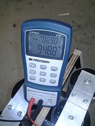
An LCR meter is a type of electronic test equipment used to measure the inductance (L), capacitance (C), and resistance (R) of an electronic component. In the simpler versions of this instrument the impedance was measured internally and converted for display to the corresponding capacitance or inductance value. Readings should be reasonably accurate if the capacitor or inductor device under test does not have a significant resistive component of impedance. More advanced designs measure true inductance or capacitance, as well as the equivalent series resistance of capacitors and the Q factor of inductive components.
The Yaesu FT-ONE is an all-mode solid state general coverage HF amateur radio (HAM) transceiver. The use of FM required an optional FM board to be installed. The unit was designed for fixed, portable or mobile operation, although the size and weight (17 kg) made it more suitable for fixed use. The FT-ONE was built by the Japanese Yaesu-Musen Corporation from 1982 to 1986. At its release, the FT-ONE was launched as the successor to the FT-902 and as the new Yaesu top-of-the-line transceiver. The FT-ONE was not only Yaesu's first fully synthesized, computer-controlled amateur band transceiver but it was also the first transceiver with a general coverage receiver. The FT-ONE was sold in the U.S., Asian and European markets. It was released in 1982 with a list price of $2800.00 US.

The Yaesu FT-817 is one of the smallest MF/HF/VHF/UHF multimode general-coverage amateur radio transceivers. The set is built by the Japanese Vertex Standard Corporation and is sold under the Yaesu brand. With internal battery pack, on board keyer, its all mode/all band capability and flexible antenna, the set is particularly well suited for portable use. The FT-817 is based on a similar circuit architecture as Yaesu's FT-857 and FT-897, so it is a compromise transceiver and incorporates its features to its low price.
The Yaesu FT-77 is a transceiver to be used in the 3,5 – 29,9 MHz shortwave radio amateur segment. This means the coverage of the 80-40-30-20-15-17-12 and 10 meter HF bands.