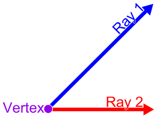
In Euclidean geometry, an angle is the figure formed by two rays, called the sides of the angle, sharing a common endpoint, called the vertex of the angle. Angles formed by two rays lie in the plane that contains the rays. Angles are also formed by the intersection of two planes. These are called dihedral angles. Two intersecting curves may also define an angle, which is the angle of the rays lying tangent to the respective curves at their point of intersection.

Technical drawing, drafting or drawing, is the act and discipline of composing drawings that visually communicate how something functions or is constructed.

Surveying or land surveying is the technique, profession, art, and science of determining the terrestrial two-dimensional or three-dimensional positions of points and the distances and angles between them. A land surveying professional is called a land surveyor. These points are usually on the surface of the Earth, and they are often used to establish maps and boundaries for ownership, locations, such as the designed positions of structural components for construction or the surface location of subsurface features, or other purposes required by government or civil law, such as property sales.

An alidade or a turning board is a device that allows one to sight a distant object and use the line of sight to perform a task. This task can be, for example, to triangulate a scale map on site using a plane table drawing of intersecting lines in the direction of the object from two or more points or to measure the angle and horizontal distance to the object from some reference point's polar measurement. Angles measured can be horizontal, vertical or in any chosen plane.

In geometry, the Schläfli symbol is a notation of the form that defines regular polytopes and tessellations.

In mathematics, a regular polytope is a polytope whose symmetry group acts transitively on its flags, thus giving it the highest degree of symmetry. All its elements or j-faces — cells, faces and so on — are also transitive on the symmetries of the polytope, and are regular polytopes of dimension ≤ n.

In geometry, the 16-cell is the regular convex 4-polytope (four-dimensional analogue of a Platonic solid) with Schläfli symbol {3,3,4}. It is one of the six regular convex 4-polytopes first described by the Swiss mathematician Ludwig Schläfli in the mid-19th century. It is also called C16, hexadecachoron, or hexdecahedroid.
The backstaff is a navigational instrument that was used to measure the altitude of a celestial body, in particular the Sun or Moon. When observing the Sun, users kept the Sun to their back and observed the shadow cast by the upper vane on a horizon vane. It was invented by the English navigator John Davis, who described it in his book Seaman's Secrets in 1594.

In geometry, a vertex figure, broadly speaking, is the figure exposed when a corner of a polyhedron or polytope is sliced off.

A caliper is a device used to measure the dimensions of an object.

The term Jacob's staff is used to refer to several things, also known as cross-staff, a ballastella, a fore-staff, a ballestilla, or a balestilha. In its most basic form, a Jacob's staff is a stick or pole with length markings; most staffs are much more complicated than that, and usually contain a number of measurement and stabilization features. The two most frequent uses are:

Gun laying is the process of aiming an artillery piece or turret, such as a gun, howitzer, or mortar, on land, in air, or at sea, against surface or aerial targets. It may be laying for direct fire, where the gun is aimed similarly to a rifle, or indirect fire, where firing data is calculated and applied to the sights. The term includes automated aiming using, for example, radar-derived target data and computer-controlled guns.
The sector, also known as a proportional compass or military compass, was a major calculating instrument in use from the end of the sixteenth century until the nineteenth century. It is an instrument consisting of two rulers of equal length joined by a hinge. A number of scales are inscribed upon the instrument which facilitate various mathematical calculations. It was used for solving problems in proportion, multiplication and division, geometry, and trigonometry, and for computing various mathematical functions, such as square roots and cube roots. Its several scales permitted easy and direct solutions of problems in gunnery, surveying and navigation. The sector derives its name from the fourth proposition of the sixth book of Euclid, where it is demonstrated that similar triangles have their like sides proportional. Some sectors also incorporated a quadrant, and sometimes a clamp at the end of one leg which allowed the device to be used as a gunner's quadrant.

In geometry, a Coxeter–Dynkin diagram is a graph with numerically labeled edges representing the spatial relations between a collection of mirrors. It describes a kaleidoscopic construction: each graph "node" represents a mirror and the label attached to a branch encodes the dihedral angle order between two mirrors, that is, the amount by which the angle between the reflective planes can be multiplied by to get 180 degrees. An unlabeled branch implicitly represents order-3, and each pair of nodes that is not connected by a branch at all represents a pair of mirrors at order-2.
A uniform polytope of dimension three or higher is a vertex-transitive polytope bounded by uniform facets. The uniform polytopes in two dimensions are the regular polygons.

In geometry, a Schlegel diagram is a projection of a polytope from into through a point just outside one of its facets. The resulting entity is a polytopal subdivision of the facet in that, together with the original facet, is combinatorially equivalent to the original polytope. The diagram is named for Victor Schlegel, who in 1886 introduced this tool for studying combinatorial and topological properties of polytopes. In dimension 3, a Schlegel diagram is a projection of a polyhedron into a plane figure; in dimension 4, it is a projection of a 4-polytope to 3-space. As such, Schlegel diagrams are commonly used as a means of visualizing four-dimensional polytopes.
Reflecting instruments are those that use mirrors to enhance their ability to make measurements. In particular, the use of mirrors permits one to observe two objects simultaneously while measuring the angular distance between the objects. While reflecting instruments are used in many professions, they are primarily associated with celestial navigation as the need to solve navigation problems, in particular the problem of the longitude, was the primary motivation in their development.

In geometry, a vertex is an angle (shape) associated with a vertex of an n-dimensional polytope. In two dimensions it refers to the angle formed by two intersecting lines, such as at a "corner" (vertex) of a polygon. In higher dimensions there can be more than two lines (edges) meeting at a vertex, making a description of the angle shape more complicated.

The Post Plotting Instrument, or simply Post Instrument, was the standard optical sighting system used by the UK's Royal Observer Corps (ROC) to determine the location of aircraft. It was used during the period from the mid-1930s into the early 1950s, and was one of the main sources of daytime tracking information during World War II.
