Related Research Articles

A backplane or backplane system is a group of electrical connectors in parallel with each other, so that each pin of each connector is linked to the same relative pin of all the other connectors, forming a computer bus. It is used to connect several printed circuit boards together to make up a complete computer system. Backplanes commonly use a printed circuit board, but wire-wrapped backplanes have also been used in minicomputers and high-reliability applications.

In telecommunications, RS-232 or Recommended Standard 232 is a standard originally introduced in 1960 for serial communication transmission of data. It formally defines signals connecting between a DTE such as a computer terminal or PC, and a DCE, such as a modem. The standard defines the electrical characteristics and timing of signals, the meaning of signals, and the physical size and pinout of connectors. The current version of the standard is TIA-232-F Interface Between Data Terminal Equipment and Data Circuit-Terminating Equipment Employing Serial Binary Data Interchange, issued in 1997.

Components of an electrical circuit are electrically connected if an electric current can run between them through an electrical conductor. An electrical connector is an electromechanical device used to create an electrical connection between parts of an electrical circuit, or between different electrical circuits, thereby joining them into a larger circuit.
A de facto standard is a custom or convention that is commonly used even though its use is not required.

Surface-mount technology (SMT), originally called planar mounting, is a method in which the electrical components are mounted directly onto the surface of a printed circuit board (PCB). An electrical component mounted in this manner is referred to as a surface-mount device (SMD). In industry, this approach has largely replaced the through-hole technology construction method of fitting components, in large part because SMT allows for increased manufacturing automation which reduces cost and improves quality. It also allows for more components to fit on a given area of substrate. Both technologies can be used on the same board, with the through-hole technology often used for components not suitable for surface mounting such as large transformers and heat-sinked power semiconductors.

Electronic test equipment is used to create signals and capture responses from electronic devices under test (DUTs). In this way, the proper operation of the DUT can be proven or faults in the device can be traced. Use of electronic test equipment is essential to any serious work on electronics systems.

A registered jack (RJ) is a standardized telecommunication network interface for connecting voice and data equipment to a computer service provided by a local exchange carrier or long distance carrier. Registered interfaces were first defined in the Universal Service Ordering Code (USOC) system of the Bell System in the United States for complying with the registration program for customer-supplied telephone equipment mandated by the Federal Communications Commission (FCC) in the 1970s. Subsequently, in 1980 they were codified in title 47 of the Code of Federal Regulations Part 68. Registered jack connections began to see use after their invention in 1973 by Bell Labs. The specification includes physical construction, wiring, and signal semantics. Accordingly, registered jacks are primarily named by the letters RJ, followed by two digits that express the type. Additional letter suffixes indicate minor variations. For example, RJ11, RJ14, and RJ25 are the most commonly used interfaces for telephone connections for one-, two-, and three-line service, respectively. Although these standards are legal definitions in the United States, some interfaces are used worldwide.
A modular connector is a type of electrical connector for cords and cables of electronic devices and appliances, such as in computer networking, telecommunication equipment, and audio headsets.
The Japan Amusement Machine and Marketing Association is a Japanese trade association headquartered in Tokyo.

Automatic test equipment or automated test equipment (ATE) is any apparatus that performs tests on a device, known as the device under test (DUT), equipment under test (EUT) or unit under test (UUT), using automation to quickly perform measurements and evaluate the test results. An ATE can be a simple computer-controlled digital multimeter, or a complicated system containing dozens of complex test instruments capable of automatically testing and diagnosing faults in sophisticated electronic packaged parts or on wafer testing, including system on chips and integrated circuits.

A computer port is a hardware piece on a computer where an electrical connector can be plugged to link the device to external devices, such as another computer, a peripheral device or network equipment.This is a non-standard term.

A cable harness, also known as a wire harness, wiring harness, cable assembly, wiring assembly or wiring loom, is an assembly of electrical cables or wires which transmit signals or electrical power. The cables are bound together by a durable material such as rubber, vinyl, electrical tape, conduit, a weave of extruded string, or a combination thereof.
A modular connector is a type of electrical connector for cords and cables of electronic devices and appliances, such as in computer networking, telecommunication equipment, and audio headsets.
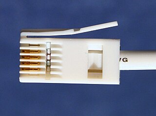
British telephone sockets were introduced in their current plug and socket form on 19 November 1981 by British Telecom to allow subscribers to connect their own telephones. The connectors are specified in British Standard BS 6312. Electrical characteristics of the telephone interface are specified by individual network operators, e.g. in British Telecom's SIN 351. Electrical characteristics required of British telephones used to be specified in BS 6305.
ESMexpress is a computer-on-module (COM) standard. It is a complete processor module that currently supports several low-power Intel and PowerPC platforms. Every module has a CPU, as well as memory and a range of serial communication interfaces such as PCI Express, Gigabit Ethernet, USB, SATA, SDVO, LVDS and HD audio. These interfaces are defined in the form factor's specification, and signals are assigned to two 120-pin connectors. This fixed pin mapping ensures that different ESMexpress modules can be exchanged more easily. Consequently, ESMexpress typically does not have an onboard FPGA. The idea behind this is to implement very specialized functions in an FPGA on the COM's carrier board to ease upgrades of the system CPU through exchange of the ESMexpress module.

Embedded System Module, or ESM, is a compact computer-on-module (COM) standard. An ESM module typically includes a CPU processor, memory, module-specific I/O interfaces and a number of basic front I/O connectors. They can be plugged on a carrier board or be used as a stand-alone processor card.
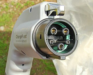
SAE J1772, also known as a J plug or Type 1 connector after its international standard, IEC 62196 Type 1, is a North American standard for electrical connectors for electric vehicles maintained by SAE International under the formal title "SAE Surface Vehicle Recommended Practice J1772, SAE Electric Vehicle Conductive Charge Coupler".
CompactPCI Serial is an industrial standard for modular computer systems. It is based on the established PICMG 2.0 CompactPCI standard, which uses the parallel PCI bus for communication among a system's card components. In contrast to this, CompactPCI Serial uses only serial point-to-point connections. CompactPCI Serial was officially adopted by the PCI Industrial Computer Manufacturers Group PICMG as PICMG CPCI-S.0 CompactPCI Serial in March 2011. Its mechanical concept is based on the proven standards of IEEE 1101-1-1998 and IEEE 1101-10-1996. CompactPCI Serial includes different connectors that permit very high data rates. The new technology standard succeeding parallel CompactPCI comprises another specification called PICMG 2.30 CompactPCI PlusIO. This is why CompactPCI Serial and CompactPCI PlusIO as a whole were also called CompactPCI Plus. PICMG's first working title of CompactPCI Serial was CPLUS.0. CompactPCI Serial backplanes and chassis are developed by Schroff, Elmа, and Pixus Technologies companies, as for the CompactPCI Serial board level electronics – they are developed by MEN Mikro Elektronik, Fastwel, EKF, Emerson Embedded Computing, ADLINK, and Kontron.
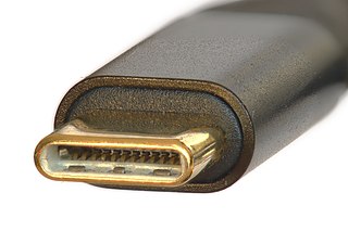
USB-C, or USB Type-C, is a 24-pin connector that supersedes previous USB connectors and can carry audio, video, and other data, to connect to monitors or external drives. It can also provide and receive power, to power, e.g., a laptop or a mobile phone. It is used not only by USB technology, but also by other protocols, including Thunderbolt, PCIe, HDMI, DisplayPort, and others. It is extensible to support future protocols.

Hermes is a machine-to-machine communication standard used in the SMT assembly industry.
References
- ↑ From Vacuum Tubes to Nanotubes: An Amazing Half Century, Published by the IPC, Edited by Michael L. Martel
- ↑ "IPC-SMEMA-9851 - Mechanical Equipment Interface Standard" (PDF). February 2007. Archived from the original (PDF) on 2016-08-12.
- ↑ "IPC-HERMES-9852: The Global Standard for Machine-to-Machine Communication in SMT Assembly". IPC. June 2019. Retrieved 2019-11-01.
- ↑ "SMEMA Mechanical Equipment Interface Standard" (PDF). Archived from the original (PDF) on 2003-04-19.
| | This electronics-related article is a stub. You can help Wikipedia by expanding it. |