The ST6 and ST7 are 8-bit microcontroller product lines from STMicroelectronics. They are commonly used in small embedded applications like washing machines.
Although they use similar peripherals and are marketed as part of the same product line, [1] [2] the two architectures are actually quite different.
Both have an 8-bit accumulator used for most operations, plus two 8-bit index registers (X and Y) used for memory addressing. Also both have 8-bit instructions followed by up to 2 bytes of operands, and both have support for manipulating and branching on individual bits of memory.
There, the similarities end.
The ST6 is a Harvard architecture with an 8-bit (256 byte) data address space and a separate 12-bit (4096 byte) program space. Operands are always 1 byte long, and some instructions support two operands, such as "move 8-bit immediate to 8-bit memory address". Subroutine calls are done using a separate hardware stack. Data registers (but not the program counter or flags) are memory-mapped.
The ST6's addressing modes are limited to immediate, 8-bit absolute memory address, and register indirect modes (X) and (Y).
The ST7 is a von Neumann architecture with a single 16-bit (64 kiB) address space. The first 256 bytes of RAM (the zero page) have extra flexibility. There are no two-operand instructions except for "test bit and branch". Its registers are not memory-mapped, and it uses general-purpose RAM (plus a stack pointer register) for subroutine calls.
The ST7 supports a wide variety of addressing modes, including base+index and double-indirect.
The ST6 has 64 bytes of RAM and 4096 bytes of program ROM. Larger amounts are accessed by bank-switching the low 2K section of the ROM.
The RAM address space is actually 256 bytes, divided as follows:
Not mapped into the address space is a 12-bit program counter and an associated hardware stack (four or six levels deep, depending on model). There are only two status bits (carry and zero), and they are banked based on processor mode, with separate status bits for normal, interrupt and non-maskable interrupt operation.
The first four general-purpose RAM locations are also known as the X, Y, V and W registers, and some instructions can access them using special short addressing modes. The X and Y registers serve as index registers, and can use indirect addressing modes (X)
and (Y)
.
The instruction set consists of one byte of opcode, followed by up to two one-byte operands. The instruction set can be summarized as follows:
7 | 6 | 5 | 4 | 3 | 2 | 1 | 0 | b2 | b3 | Mnemonic | C | Z | Description |
---|---|---|---|---|---|---|---|---|---|---|---|---|---|
offset | opc | 0 | — | — | Conditional branches (5-bit PC-relative) | ||||||||
offset | 0 | 0 | 0 | — | — | JRNZ address | Jump to PC + simm5 if Z == 0 | ||||||
offset | 1 | 0 | 0 | — | — | JRZ address | Jump to PC + simm5 if Z == 1 | ||||||
offset | 0 | 1 | 0 | — | — | JRNC address | Jump to PC + simm5 if C == 0 | ||||||
offset | 1 | 1 | 0 | — | — | JRC address | Jump to PC + simm5 if C == 1 | ||||||
imm4 | c | 0 | 0 | 1 | imm8 | — | Unconditional branches (12-bit absolute) | ||||||
imm4 | 0 | 0 | 0 | 1 | imm8 | — | CALL imm12 | Push PC, jump to 12-bit address | |||||
imm4 | 1 | 0 | 0 | 1 | imm8 | — | JP imm12 | Jump to 12-bit address | |||||
— | 0 | 0 | 1 | 0 | 1 | — | — | (reserved) | |||||
reg | c | 1 | c | 1 | 0 | 1 | — | — | Register operations (on X, Y, V or W) | ||||
reg | 0 | 1 | 0 | 1 | 0 | 1 | — | — | INC reg | Z | Increment register. Z is set, C is not. | ||
reg | 1 | 1 | 0 | 1 | 0 | 1 | — | — | LD A,reg | Z | A := {X, Y, V or W} | ||
reg | 0 | 1 | 1 | 1 | 0 | 1 | — | — | DEC reg | Z | Decrement register. Z is set, C is not. | ||
reg | 1 | 1 | 1 | 1 | 0 | 1 | — | — | LD reg,A | Z | {X, Y, V or W} := A | ||
opcode | 0 | 1 | 1 | 0 | 1 | — | — | Miscellaneous operations | |||||
0 | 0 | 0 | 0 | 1 | 1 | 0 | 1 | addr | imm8 | LDI addr,imm8 | Set RAM to 8-bit immediate value | ||
1 | 0 | 0 | 0 | 1 | 1 | 0 | 1 | — | — | (reserved) | |||
0 | 1 | 0 | 0 | 1 | 1 | 0 | 1 | — | — | RETI | Return from interrupt. Pop PC, restore flags. | ||
1 | 1 | 0 | 0 | 1 | 1 | 0 | 1 | — | — | RET | Return from subroutine. Pop PC from hardware stack. | ||
0 | 0 | 1 | 0 | 1 | 1 | 0 | 1 | — | — | COM A | Z | C | Complement: C := msbit(A); A := ~A |
1 | 0 | 1 | 0 | 1 | 1 | 0 | 1 | — | — | RLC A | C | A := A + A + C | |
0 | 1 | 1 | 0 | 1 | 1 | 0 | 1 | — | — | STOP | Halt processor, clock, most peripherals until next interrupt | ||
1 | 1 | 1 | 0 | 1 | 1 | 0 | 1 | — | — | WAIT | Halt processor until next interrupt; clock continues | ||
bit | opc | 0 | 1 | 1 | address | ? | Bit operations (absolute address only) | ||||||
bit | 0 | 0 | 0 | 1 | 1 | src | simm8 | JRR bit,src,address | C | C := src.bit; jump to PC+simm8 if reset (clear) | |||
bit | 1 | 0 | 0 | 1 | 1 | src | simm8 | JRS bit,src,address | C | C := src.bit; jump to PC+simm8 if set | |||
bit | 0 | 1 | 0 | 1 | 1 | dst | — | RES bit,dst | Reset (set to 0) dst.bit | ||||
bit | 1 | 1 | 0 | 1 | 1 | dst | — | SET bit,dst | Set (to 1) dst.bit | ||||
opcode | data | 1 | 1 | 1 | ? | — | ALU operations with RAM or immediate | ||||||
opcode | 0 | 0 | 1 | 1 | 1 | — | — | (X) | Operand is (X) | ||||
opcode | 0 | 1 | 1 | 1 | 1 | — | — | (Y) | Operand is (Y) | ||||
opcode | 1 | 0 | 1 | 1 | 1 | imm8 | — | imm8 | Operand is 8-bit immediate (source only) | ||||
opcode | 1 | 1 | 1 | 1 | 1 | addr | — | addr | Operand is 8-bit RAM address | ||||
0 | 0 | 0 | src | 1 | 1 | 1 | ? | — | LD A,src | Z | A := src | ||
1 | 0 | 0 | dst | 1 | 1 | 1 | ? | — | LD dst,A | Z | dst := A (immediate forbidden) | ||
0 | 1 | 0 | src | 1 | 1 | 1 | ? | — | ADD A,src | Z | C | A := A + src | |
1 | 1 | 0 | src | 1 | 1 | 1 | ? | — | SUB A,src | Z | C † | A := A − src | |
0 | 0 | 1 | src | 1 | 1 | 1 | ? | — | CP A,src | Z | C † | A − src | |
1 | 0 | 1 | src | 1 | 1 | 1 | ? | — | AND A,src | Z | A := A &src | ||
0 | 1 | 1 | dst | 1 | 1 | 1 | ? | — | INC dst | Z | dst := dst + 1 (immediate forbidden) | ||
1 | 1 | 1 | dst | 1 | 1 | 1 | ? | — | DEC dst | Z | dst := dst − 1 (immediate forbidden) |
†: ^ a b Confusingly, different models of the ST6 family use different conventions for the value of the carry bit after a subtraction. ST60 processors use the "carry" convention, which clears the bit if the subtract underflows, while the ST62 and ST63 processors use the "borrow" convention, which sets the bit in that case. [3] : 21–22,42
The ST7 has six registers: the accumulator, X and Y index registers, stack pointer, program counter, and condition code register. Also, double-indirect addressing allows the zero page of RAM to serve as additional registers. An unusual but useful feature is that an interrupt pushes four of these registers on the stack (A and X as well as the usual PC and CC), and interrupt return restores them.
ALU instructions fall into two categories, two-operand and one-operand.
Two-operand instructions use the accumulator as the first source. The addressing mode specifies the second source, which may be:
The destination is usually the accumulator, but a few instructions modify the second source. (Immediate operands are forbidden in such cases.)
One-operand instructions use the specified operand for both source and destination. The operand may be:
Register plus offset computes a full-width sum, so the 8-bit form may address memory up to 255+255 = 510.
In addition to the above, there are three prefix bytes which may be prepended to any instruction for which they make sense:
7 | 6 | 5 | 4 | 3 | 2 | 1 | 0 | b2 | b3 | Mnemonic | Description |
---|---|---|---|---|---|---|---|---|---|---|---|
0 | 0 | 0 | c | bit | v | address | ? | Bit operations | |||
0 | 0 | 0 | 0 | bit | 0 | addr8 | soff8 | BTJT addr8,#bit,label | Jump to PC + soff8 if source bit is true (set) | ||
0 | 0 | 0 | 0 | bit | 1 | addr8 | soff8 | BTJF addr8,#bit,label | Jump to PC + soff8 if source bit is false (clear) | ||
0 | 0 | 0 | 1 | bit | 0 | addr8 | — | BSET addr8,#bit | Set specified bit to 1 | ||
0 | 0 | 0 | 1 | bit | 1 | addr8 | — | BRES addr8,#bit | Reset (clear) specified bit to 0 | ||
0 | 0 | 1 | 0 | condition | soff8 | — | Conditional branches (8-bit relative offset) | ||||
0 | 0 | 1 | 0 | 0 | 0 | 0 | 0 | soff8 | — | JRA label | Branch always (true) |
0 | 0 | 1 | 0 | 0 | 0 | 0 | 1 | soff8 | — | JRF label | Branch never (false) |
0 | 0 | 1 | 0 | 0 | 0 | 1 | 0 | soff8 | — | JRUGT label | Branch if unsigned greater than (C=0 and Z=0) |
0 | 0 | 1 | 0 | 0 | 0 | 1 | 1 | soff8 | — | JRULE label | Branch if unsigned less than or equal (C=1 or Z=1) |
0 | 0 | 1 | 0 | 0 | 1 | 0 | 0 | soff8 | — | JRNC label | Branch if no carry (C=0) |
0 | 0 | 1 | 0 | 0 | 1 | 0 | 1 | soff8 | — | JRC label | Branch if carry (C=1) |
0 | 0 | 1 | 0 | 0 | 1 | 1 | 0 | soff8 | — | JRNE label | Branch if not equal (Z=0) |
0 | 0 | 1 | 0 | 0 | 1 | 1 | 1 | soff8 | — | JREQ label | Branch if equal (Z=1) |
0 | 0 | 1 | 0 | 1 | 0 | 0 | 0 | soff8 | — | JRNH label | Branch if not half-carry (H=0) |
0 | 0 | 1 | 0 | 1 | 0 | 0 | 1 | soff8 | — | JRH label | Branch if half-carry (H=1) |
0 | 0 | 1 | 0 | 1 | 0 | 1 | 0 | soff8 | — | JRPL label | Branch if plus (N=0) |
0 | 0 | 1 | 0 | 1 | 0 | 1 | 1 | soff8 | — | JRMI label | Branch if minus (N=1) |
0 | 0 | 1 | 0 | 1 | 1 | 0 | 0 | soff8 | — | JRNM label | Branch if not interrupt mask (M=0) |
0 | 0 | 1 | 0 | 1 | 1 | 0 | 1 | soff8 | — | JRM label | Branch if interrupts masked (M=1) |
0 | 0 | 1 | 0 | 1 | 1 | 1 | 0 | soff8 | — | JRIL label | Branch if interrupt line is low |
0 | 0 | 1 | 0 | 1 | 1 | 1 | 1 | soff8 | — | JRIH label | Branch if interrupt line is high |
0 | mode | opcode | ? | — | One-operand instructions | ||||||
0 | 0 | 1 | 1 | opcode | addr8 | — | OP addr8 | 8-bit absolute address | |||
0 | 1 | 0 | 0 | opcode | — | — | OP A | Accumulator | |||
0 | 1 | 0 | 1 | opcode | — | — | OP X | X register (Y register with prefix) | |||
0 | 1 | 1 | 0 | opcode | addr8 | — | OP (addr8,X) | 8-bit address plus X | |||
0 | 1 | 1 | 1 | opcode | — | — | OP (X) | Indexed with no offset | |||
0 | mode | 0 | 0 | 0 | 0 | ? | — | NEG operand | Two's-complement negate | ||
0 | mode | 0 | 0 | 0 | 1 | ? | — | (reserved) | |||
0 | mode | 0 | 0 | 1 | 0 | ? | — | (reserved) | |||
0 | 1 | 0 | 0 | 0 | 0 | 1 | 0 | — | — | MUL X,A | X:A := X × A. (MUL Y,A with prefix) |
0 | mode | 0 | 0 | 1 | 1 | ? | — | CPL operand | Ones' complement, logical not | ||
0 | mode | 0 | 1 | 0 | 0 | ? | — | SRL operand | Shift right logical. Msbit cleared, lsbit to carry. | ||
0 | mode | 0 | 1 | 0 | 1 | ? | — | (reserved) | |||
0 | mode | 0 | 1 | 1 | 0 | ? | — | RRC operand | Rotate right through carry, (operand:C) := (C:operand) | ||
0 | mode | 0 | 1 | 1 | 1 | ? | — | SRA operand | Shift right arithmetic. Msbit preserved, lebit to carry. | ||
0 | mode | 1 | 0 | 0 | 0 | ? | — | SLL operand | Shift left. Msbit to carry. | ||
0 | mode | 1 | 0 | 0 | 1 | ? | — | RLC operand | Rotate left through carry. | ||
0 | mode | 1 | 0 | 1 | 0 | ? | — | DEC operand | Decrement. (N and Z set, carry unaffected) | ||
0 | mode | 1 | 0 | 1 | 1 | ? | — | (reserved) | |||
0 | mode | 1 | 1 | 0 | 0 | ? | — | INC operand | Increment. (N and Z set, carry unaffected) | ||
0 | mode | 1 | 1 | 0 | 1 | ? | — | TNZ operand | Test non-zero. Set N and Z based on operand. | ||
0 | mode | 1 | 1 | 1 | 0 | ? | — | SWAP operand | Swap halves of operand (4-bit rotate). | ||
0 | mode | 1 | 1 | 1 | 1 | ? | — | CLR operand | Set operand to 0. N and Z set to fixed values.operand. | ||
1 | 0 | 0 | opcode | — | — | Miscellaneous instructions. None implicitly set the condition codes. | |||||
1 | 0 | 0 | 0 | 0 | 0 | 0 | 0 | — | — | IRET | Return from interrupt (pop CC, A, X, PC) |
1 | 0 | 0 | 0 | 0 | 0 | 0 | 1 | — | — | RET | Return from subroutine (pop PC) |
1 | 0 | 0 | 0 | 0 | 0 | 1 | 0 | — | — | TRAP | Force trap interrupt |
1 | 0 | 0 | 0 | 0 | 0 | 1 | 1 | — | — | (reserved) | |
1 | 0 | 0 | 0 | 0 | 1 | 0 | 0 | — | — | POP A | Pop A from stack |
1 | 0 | 0 | 0 | 0 | 1 | 0 | 1 | — | — | POP X | Pop X from stack |
1 | 0 | 0 | 0 | 0 | 1 | 1 | 0 | — | — | POP CC | Pop condition codes from stack |
1 | 0 | 0 | 0 | 0 | 1 | 1 | 1 | — | — | (reserved) | |
1 | 0 | 0 | 0 | 1 | 0 | 0 | 0 | — | — | PUSH A | Push A onto stack |
1 | 0 | 0 | 0 | 1 | 0 | 0 | 1 | — | — | PUSH X | Push X onto stack |
1 | 0 | 0 | 0 | 1 | 0 | 1 | 0 | — | — | PUSH CC | Push condition codes onto stack |
1 | 0 | 0 | 0 | 1 | 0 | 1 | 1 | — | — | (reserved) | |
1 | 0 | 0 | 0 | 1 | 1 | 0 | — | — | — | (reserved) | |
1 | 0 | 0 | 0 | 1 | 1 | 1 | 0 | — | — | HALT | Halt processor and clocks |
1 | 0 | 0 | 0 | 1 | 1 | 1 | 1 | — | — | WFI | Wait for interrupt, halting processor but not clocks |
1 | 0 | 0 | 1 | 0 | 0 | 0 | 0 | — | — | PDY | Instruction prefix; swap X and Y in next instruction |
1 | 0 | 0 | 1 | 0 | 0 | 0 | 1 | — | — | PIY | Instruction prefix; PDY plus PIX |
1 | 0 | 0 | 1 | 0 | 0 | 1 | 0 | — | — | PIX | Instruction prefix; use 8-bit memory indirect for operand |
1 | 0 | 0 | 1 | 0 | 0 | 1 | 1 | — | — | LD X,Y | X := Y. With PDY, does "LD Y,X". |
1 | 0 | 0 | 1 | 0 | 1 | 0 | 0 | — | — | LD S,X | S := X. Load stack pointer. |
1 | 0 | 0 | 1 | 0 | 1 | 0 | 1 | — | — | LD S,A | S := A. Load stack pointer. |
1 | 0 | 0 | 1 | 0 | 1 | 1 | 0 | — | — | LD X,S | X := S. |
1 | 0 | 0 | 1 | 0 | 1 | 1 | 1 | — | — | LD X,A | X := A. |
1 | 0 | 0 | 1 | 1 | 0 | 0 | 0 | — | — | RCF | Reset (clear) carry flag |
1 | 0 | 0 | 1 | 1 | 0 | 0 | 1 | — | — | SCF | Set carry flag |
1 | 0 | 0 | 1 | 1 | 0 | 1 | 0 | — | — | RIM | Reset interrupt mask (enable interrupts) |
1 | 0 | 0 | 1 | 1 | 0 | 1 | 1 | — | — | SIM | Set interrupt mask (disable interrupts) |
1 | 0 | 0 | 1 | 1 | 1 | 0 | 0 | — | — | RSP | Reset stack pointer (to top of RAM) |
1 | 0 | 0 | 1 | 1 | 1 | 0 | 1 | — | — | NOP | No operation. (=LD A,A) |
1 | 0 | 0 | 1 | 1 | 1 | 1 | 0 | — | — | LD A,S | A := S |
1 | 0 | 0 | 1 | 1 | 1 | 1 | 1 | — | — | LD A,X | A := X. |
1 | mode | opcode | value | ? | Two-operand instructions A := A op operand | ||||||
1 | 0 | 1 | 0 | opcode | imm8 | — | OP #imm8 | 8-bit immediate operand (forbidden as destination) | |||
1 | 0 | 1 | 1 | opcode | addr8 | — | OP addr8 | 8-bit absolute address | |||
1 | 1 | 0 | 0 | opcode | addrhi | addrlo | OP addr16 | 16-bit absolute address | |||
1 | 1 | 0 | 1 | opcode | addrhi | addrlo | OP (addr16,X) | Indexed with 16-bit offset | |||
1 | 1 | 1 | 0 | opcode | addr8 | — | OP (addr8,X) | Indexed with 8-bit offset | |||
1 | 1 | 1 | 1 | opcode | — | — | OP (X) | Indexed with no offset | |||
1 | mode | 0 | 0 | 0 | 0 | value | ? | SUB A,operand | A := A − operand | ||
1 | mode | 0 | 0 | 0 | 1 | value | ? | CP A,operand | Compare A − operand | ||
1 | mode | 0 | 0 | 1 | 0 | value | ? | SBC A,operand | Subtract with borrow A := A − operand − C | ||
1 | mode | 0 | 0 | 1 | 1 | value | ? | CP X,operand | Compare X − operand | ||
1 | mode | 0 | 1 | 0 | 0 | value | ? | AND A,operand | A := A & operand, bitwise and | ||
1 | mode | 0 | 1 | 0 | 1 | value | ? | BCP A,operand | Bitwise test A & operand | ||
1 | mode | 0 | 1 | 1 | 0 | value | ? | LD A,operand | Load A := operand | ||
1 | 0 | 1 | 0 | 0 | 1 | 1 | 1 | imm8 | — | (reserved, =LD #imm8,A) | |
1 | mode | 0 | 1 | 1 | 1 | value | ? | LD operand,A | Store operand := A | ||
1 | mode | 1 | 0 | 0 | 0 | value | ? | XOR A,operand | A := A ^ operand, exclusive-or | ||
1 | mode | 1 | 0 | 0 | 1 | value | ? | ADC A,operand | A := A + operand + C, add with carry | ||
1 | mode | 1 | 0 | 1 | 0 | value | ? | OR A,operand | A := A | operand, inclusive or | ||
1 | mode | 1 | 0 | 1 | 1 | value | ? | ADD X,operand | A := A + operand | ||
1 | 0 | 1 | 0 | 1 | 1 | 0 | 0 | imm8 | x | (reserved, =JP #imm8) | |
1 | mode | 1 | 1 | 0 | 0 | value | ? | JP operand | PC := operand, unconditional jump | ||
1 | 0 | 1 | 0 | 1 | 1 | 0 | 1 | soff8 | — | CALLR label | PUSH PC, PC := PC + operand |
1 | mode | 1 | 1 | 0 | 1 | value | ? | CALL operand | Push PC, PC := operand | ||
1 | mode | 1 | 1 | 1 | 0 | value | ? | LD X,operand | Load X := operand | ||
1 | 0 | 1 | 0 | 1 | 1 | 1 | 1 | imm8 | — | (reserved, =LD #imm8,X) | |
1 | mode | 1 | 1 | 1 | 1 | value | ? | LD operand,X | Store operand := X |
The 68HC11 is an 8-bit microcontroller (µC) family introduced by Motorola in 1984. Now produced by NXP Semiconductors, it descended from the Motorola 6800 microprocessor by way of the 6801. It is a CISC microcontroller. The 68HC11 devices are more powerful and more expensive than the 68HC08 microcontrollers, and are used in automotive applications, barcode readers, hotel card key writers, amateur robotics, and various other embedded systems. The MC68HC11A8 was the first microcontroller to include CMOS EEPROM.
x86 is a family of instruction set architectures initially developed by Intel based on the Intel 8086 microprocessor and its 8088 variant. The 8086 was introduced in 1978 as a fully 16-bit extension of Intel's 8-bit 8080 microprocessor, with memory segmentation as a solution for addressing more memory than can be covered by a plain 16-bit address. The term "x86" came into being because the names of several successors to Intel's 8086 processor end in "86", including the 80186, 80286, 80386 and 80486 processors.
The Z80 is an 8-bit microprocessor introduced by Zilog as the startup company's first product. The Z80 was conceived by Federico Faggin in late 1974 and developed by him and his 11 employees starting in early 1975. The first working samples were delivered in March 1976, and it was officially introduced on the market in July 1976. With the revenue from the Z80, the company built its own chip factories and grew to over a thousand employees over the following two years.
In computer science, an instruction set architecture (ISA), also called computer architecture, is an abstract model of a computer. A device that executes instructions described by that ISA, such as a central processing unit (CPU), is called an implementation.
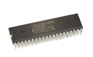
The Intel MCS-51 is a single chip microcontroller (MCU) series developed by Intel in 1980 for use in embedded systems. The architect of the Intel MCS-51 instruction set was John H. Wharton. Intel's original versions were popular in the 1980s and early 1990s, and enhanced binary compatible derivatives remain popular today. It is an example of a complex instruction set computer and has separate memory spaces for program instructions and data.
PIC is a family of microcontrollers made by Microchip Technology, derived from the PIC1650 originally developed by General Instrument's Microelectronics Division. The name PIC initially referred to Peripheral Interface Controller, and is currently expanded as Programmable Intelligent Computer. The first parts of the family were available in 1976; by 2013 the company had shipped more than twelve billion individual parts, used in a wide variety of embedded systems.
x86 assembly language is a family of backward-compatible assembly languages, which provide some level of compatibility all the way back to the Intel 8008 introduced in April 1972. x86 assembly languages are used to produce object code for the x86 class of processors. Like all assembly languages, it uses short mnemonics to represent the fundamental instructions that the CPU in a computer can understand and follow. Compilers sometimes produce assembly code as an intermediate step when translating a high level program into machine code. Regarded as a programming language, assembly coding is machine-specific and low level. Assembly languages are more typically used for detailed and time critical applications such as small real-time embedded systems or operating system kernels and device drivers.
Addressing modes are an aspect of the instruction set architecture in most central processing unit (CPU) designs. The various addressing modes that are defined in a given instruction set architecture define how the machine language instructions in that architecture identify the operand(s) of each instruction. An addressing mode specifies how to calculate the effective memory address of an operand by using information held in registers and/or constants contained within a machine instruction or elsewhere.
The COP8 microcontroller from National Semiconductor is an 8-bit CISC core microcontroller, whose main features are:
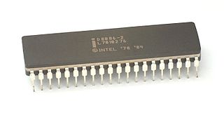
Introduced in June 1976, the TMS9900 was one of the first commercially available, single-chip 16-bit microprocessors. It implemented Texas Instruments' TI-990 minicomputer architecture in a single-chip format, and was initially used for low-end models of that lineup.
In computer engineering, an orthogonal instruction set is an instruction set architecture where all instruction types can use all addressing modes. It is "orthogonal" in the sense that the instruction type and the addressing mode vary independently. An orthogonal instruction set does not impose a limitation that requires a certain instruction to use a specific register so there is little overlapping of instruction functionality.
The Atmel AVR instruction set is the machine language for the Atmel AVR, a modified Harvard architecture 8-bit RISC single chip microcontroller which was developed by Atmel in 1996. The AVR was one of the first microcontroller families to use on-chip flash memory for program storage.
The Western Design Center (WDC) 65C02 microprocessor is an enhanced CMOS version of the popular nMOS-based 8-bit MOS Technology 6502. The 65C02 fixed several problems in the original 6502 and added some new instructions, but its main feature was greatly lowered power usage, on the order of 10 to 20 times less than the original 6502 running at the same speed. The reduced power consumption made the 65C02 useful in portable computer roles and microcontroller systems in industrial settings. It has been used in some home computers, as well as in embedded applications, including medical-grade implanted devices.
The CSG 65CE02 is an 8/16-bit microprocessor developed by Commodore Semiconductor Group in 1988. It is a member of the MOS Technology 6502 family, developed from the CMOS WDC 65C02 released by the Western Design Center in 1983.
The TI-990 was a series of 16-bit minicomputers sold by Texas Instruments (TI) in the 1970s and 1980s. The TI-990 was a replacement for TI's earlier minicomputer systems, the TI-960 and the TI-980. It had several unique features, and was easier to program than its predecessors. Among its core concepts was the ability to easily support multiprogramming using a software-switchable set of processor registers that allowed it to perform rapid context switches between programs.
The PDP-11 architecture is a CISC instruction set architecture (ISA) developed by Digital Equipment Corporation (DEC). It is implemented by central processing units (CPUs) and microprocessors used in PDP-11 minicomputers. It was in wide use during the 1970s, but was eventually overshadowed by the more powerful VAX-11 architecture in the 1980s.
The W65C816S is an 8/16-bit microprocessor (MPU) developed and sold by the Western Design Center (WDC). Introduced in 1983, the W65C816S is an enhanced version of the WDC 65C02 8-bit MPU, itself a CMOS enhancement of the venerable MOS Technology 6502 NMOS MPU. The 65C816 was the CPU for the Apple IIGS and, in modified form, the Super Nintendo Entertainment System.
The PIC instruction set refers to the set of instructions that Microchip Technology PIC or dsPIC microcontroller supports. The instructions are usually programmed into the Flash memory of the processor, and automatically executed by the microcontroller on startup.
The STM8 is an 8-bit microcontroller family by STMicroelectronics. The STM8 microcontrollers use an extended variant of the ST7 microcontroller architecture. STM8 microcontrollers are particularly low cost for a full-featured 8-bit microcontroller.
The WD16 is a 16-bit microprocessor introduced by Western Digital in October 1976. It is based on the MCP-1600 chipset, which formed the basis of the DEC LSI-11 low-end minicomputer and the Pascal MicroEngine processor designed specifically to run the UCSD p-System efficiently. Each used different microcode. The WD16 implements an extension of the PDP-11 instruction set architecture but is not machine code compatible with the PDP-11. The WD16 is an extreme example of CISC architecture. Most two-operand instructions can operate memory-to-memory and some instructions can result in up to ten memory accesses.