Related Research Articles

In physics, interference is a phenomenon in which two coherent waves are combined by adding their intensities or displacements with due consideration for their phase difference. The resultant wave may have greater intensity or lower amplitude if the two waves are in phase or out of phase, respectively. Interference effects can be observed with all types of waves, for example, light, radio, acoustic, surface water waves, gravity waves, or matter waves as well as in loudspeakers as electrical waves.

In optics, the refractive index of an optical medium is the ratio of the apparent speed of light in the air or vacuum to the speed in the medium. The refractive index determines how much the path of light is bent, or refracted, when entering a material. This is described by Snell's law of refraction, n1 sin θ1 = n2 sin θ2, where θ1 and θ2 are the angle of incidence and angle of refraction, respectively, of a ray crossing the interface between two media with refractive indices n1 and n2. The refractive indices also determine the amount of light that is reflected when reaching the interface, as well as the critical angle for total internal reflection, their intensity and Brewster's angle.
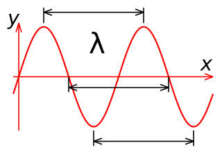
In physics and mathematics, wavelength or spatial period of a wave or periodic function is the distance over which the wave's shape repeats. In other words, it is the distance between consecutive corresponding points of the same phase on the wave, such as two adjacent crests, troughs, or zero crossings. Wavelength is a characteristic of both traveling waves and standing waves, as well as other spatial wave patterns. The inverse of the wavelength is called the spatial frequency. Wavelength is commonly designated by the Greek letter lambda (λ). The term "wavelength" is also sometimes applied to modulated waves, and to the sinusoidal envelopes of modulated waves or waves formed by interference of several sinusoids.
In electrical engineering, electrical length is a dimensionless parameter equal to the physical length of an electrical conductor such as a cable or wire, divided by the wavelength of alternating current at a given frequency traveling through the conductor. In other words, it is the length of the conductor measured in wavelengths. It can alternately be expressed as an angle, in radians or degrees, equal to the phase shift the alternating current experiences traveling through the conductor.
In electrical engineering, a ground plane is an electrically conductive surface, usually connected to electrical ground.
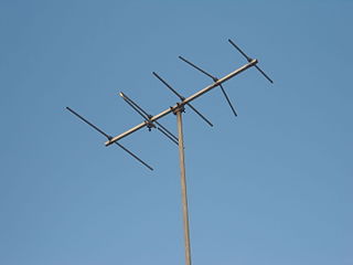
In radio engineering, an antenna or aerial is an electronic device that converts an alternating electric current into radio waves (transmitting), or radio waves into an electric current (receiving). It is the interface between radio waves propagating through space and electric currents moving in metal conductors, used with a transmitter or receiver. In transmission, a radio transmitter supplies an electric current to the antenna's terminals, and the antenna radiates the energy from the current as electromagnetic waves. In reception, an antenna intercepts some of the power of a radio wave in order to produce an electric current at its terminals, that is applied to a receiver to be amplified. Antennas are essential components of all radio equipment.

An anechoic chamber is a room designed to stop reflections or echoes of either sound or electromagnetic waves. They are also often isolated from energy entering from their surroundings. This combination means that a person or detector exclusively hears direct sounds, in effect simulating being outside in a free field.

An optical coating is one or more thin layers of material deposited on an optical component such as a lens, prism or mirror, which alters the way in which the optic reflects and transmits light. These coatings have become a key technology in the field of optics. One type of optical coating is an anti-reflective coating, which reduces unwanted reflections from surfaces, and is commonly used on spectacle and camera lenses. Another type is the high-reflector coating, which can be used to produce mirrors that reflect greater than 99.99% of the light that falls on them. More complex optical coatings exhibit high reflection over some range of wavelengths, and anti-reflection over another range, allowing the production of dichroic thin-film filters.
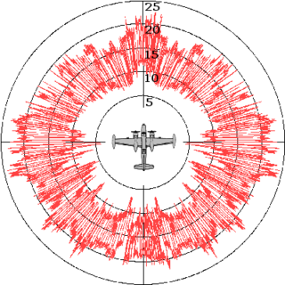
Radar cross-section (RCS), denoted σ, also called radar signature, is a measure of how detectable an object is by radar. A larger RCS indicates that an object is more easily detected.
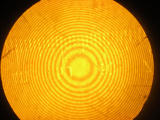
Newton's rings is a phenomenon in which an interference pattern is created by the reflection of light between two surfaces, typically a spherical surface and an adjacent touching flat surface. It is named after Isaac Newton, who investigated the effect in 1666. When viewed with monochromatic light, Newton's rings appear as a series of concentric, alternating bright and dark rings centered at the point of contact between the two surfaces. When viewed with white light, it forms a concentric ring pattern of rainbow colors because the different wavelengths of light interfere at different thicknesses of the air layer between the surfaces.

Ellipsometry is an optical technique for investigating the dielectric properties of thin films. Ellipsometry measures the change of polarization upon reflection or transmission and compares it to a model.
Plasma stealth is a proposed process to use ionized gas (plasma) to reduce the radar cross-section (RCS) of an aircraft. Interactions between electromagnetic radiation and ionized gas have been extensively studied for many purposes, including concealing aircraft from radar as stealth technology. Various methods might plausibly be able to form a layer or cloud of plasma around a vehicle to deflect or absorb radar, from simpler electrostatic or radio frequency discharges to more complex laser discharges. It is theoretically possible to reduce RCS in this way, but it may be very difficult to do so in practice. Some Russian missiles e.g. the 3M22 Zircon (SS-N-33) and Kh-47M2 Kinzhal missiles have been reported to make use of plasma stealth.

A polarizer or polariser is an optical filter that lets light waves of a specific polarization pass through while blocking light waves of other polarizations. It can filter a beam of light of undefined or mixed polarization into a beam of well-defined polarization, known as polarized light. Polarizers are used in many optical techniques and instruments. Polarizers find applications in photography and LCD technology. In photography, a polarizing filter can be used to filter out reflections.

In radio-frequency engineering and communications engineering, a waveguide is a hollow metal pipe used to carry radio waves. This type of waveguide is used as a transmission line mostly at microwave frequencies, for such purposes as connecting microwave transmitters and receivers to their antennas, in equipment such as microwave ovens, radar sets, satellite communications, and microwave radio links.

In materials science, radiation-absorbent material (RAM) is a material which has been specially designed and shaped to absorb incident RF radiation, as effectively as possible, from as many incident directions as possible. The more effective the RAM, the lower the resulting level of reflected RF radiation. Many measurements in electromagnetic compatibility (EMC) and antenna radiation patterns require that spurious signals arising from the test setup, including reflections, are negligible to avoid the risk of causing measurement errors and ambiguities.

An optical flat is an optical-grade piece of glass lapped and polished to be extremely flat on one or both sides, usually within a few tens of nanometres. They are used with a monochromatic light to determine the flatness of other surfaces, by means of wave interference.
X-ray optics is the branch of optics dealing with X-rays, rather than visible light. It deals with focusing and other ways of manipulating the X-ray beams for research techniques such as X-ray diffraction, X-ray crystallography, X-ray fluorescence, small-angle X-ray scattering, X-ray microscopy, X-ray phase-contrast imaging, and X-ray astronomy.
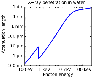
Penetration depth is a measure of how deep light or any electromagnetic radiation can penetrate into a material. It is defined as the depth at which the intensity of the radiation inside the material falls to 1/e of its original value at the surface.

Thin-film interference is a natural phenomenon in which light waves reflected by the upper and lower boundaries of a thin film interfere with one another, increasing reflection at some wavelengths and decreasing it at others. When white light is incident on a thin film, this effect produces colorful reflections.
Electromagnetic absorbers are specifically chosen or designed materials that can inhibit the reflection or transmission of electromagnetic radiation. For example, this can be accomplished with materials such as dielectrics combined with metal plates spaced at prescribed intervals or wavelengths. The particular absorption frequencies, thickness, component arrangement and configuration of the materials also determine capabilities and uses. In addition, researchers are studying advanced materials such as metamaterials in hopes of improved performance and diversity of applications. Some intended applications for the new absorbers include emitters, sensors, spatial light modulators, infrared camouflage, wireless communication, and use in thermophotovoltaics.
References
- ↑ Munk, Benedikt A (2000). Frequency Selective Surfaces: Theory and Design. New York: John Wiley & Sons. pp. 315–317. ISBN 0-471-37047-9.
- ↑ (A) US 2599944 (A) "Absorbent body for electromagnetic waves". Salisbury W. W. June 10, 1952, cited in Munk