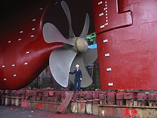
A propeller is a device with a rotating hub and radiating blades that are set at a pitch to form a helical spiral which, when rotated, exerts linear thrust upon a working fluid such as water or air. Propellers are used to pump fluid through a pipe or duct, or to create thrust to propel a boat through water or an aircraft through air. The blades are shaped so that their rotational motion through the fluid causes a pressure difference between the two surfaces of the blade by Bernoulli's principle which exerts force on the fluid. Most marine propellers are screw propellers with helical blades rotating on a propeller shaft with an approximately horizontal axis.

Thrust is a reaction force described quantitatively by Newton's third law. When a system expels or accelerates mass in one direction, the accelerated mass will cause a force of equal magnitude but opposite direction to be applied to that system. The force applied on a surface in a direction perpendicular or normal to the surface is also called thrust. Force, and thus thrust, is measured using the International System of Units (SI) in newtons, and represents the amount needed to accelerate 1 kilogram of mass at the rate of 1 meter per second per second. In mechanical engineering, force orthogonal to the main load is referred to as static thrust.

Propulsion is the generation of force by any combination of pushing or pulling to modify the translational motion of an object, which is typically a rigid body but may also concern a fluid. The term is derived from two Latin words: pro, meaning before or forward; and pellere, meaning to drive. A propulsion system consists of a source of mechanical power, and a propulsor.
Fluid bearings are bearings in which the load is supported by a thin layer of rapidly moving pressurized liquid or gas between the bearing surfaces. Since there is no contact between the moving parts, there is no sliding friction, allowing fluid bearings to have lower friction, wear and vibration than many other types of bearings. Thus, it is possible for some fluid bearings to have near-zero wear if operated correctly.
In continuum mechanics, the Froude number is a dimensionless number defined as the ratio of the flow inertia to the external field. The Froude number is based on the speed–length ratio which he defined as:
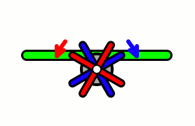
Blade element theory (BET) is a mathematical process originally designed by William Froude (1878), David W. Taylor (1893) and Stefan Drzewiecki (1885) to determine the behavior of propellers. It involves breaking a blade down into several small parts then determining the forces on each of these small blade elements. These forces are then integrated along the entire blade and over one rotor revolution in order to obtain the forces and moments produced by the entire propeller or rotor. One of the key difficulties lies in modelling the induced velocity on the rotor disk. Because of this the blade element theory is often combined with momentum theory to provide additional relationships necessary to describe the induced velocity on the rotor disk, producing blade element momentum theory. At the most basic level of approximation a uniform induced velocity on the disk is assumed:

A ship model basin is a basin or tank used to carry out hydrodynamic tests with ship models, for the purpose of designing a new ship, or refining the design of a ship to improve the ship's performance at sea. It can also refer to the organization that owns and operates such a facility.
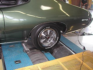
A dynamometer or "dyno" for short, is a device for simultaneously measuring the torque and rotational speed (RPM) of an engine, motor or other rotating prime mover so that its instantaneous power may be calculated, and usually displayed by the dynamometer itself as kW or bhp.
Aircraft equipped with contra-rotating propellers (CRP) coaxial contra-rotating propellers, or high-speed propellers, apply the maximum power of usually a single piston engine or turboprop engine to drive a pair of coaxial propellers in contra-rotation. Two propellers are arranged one behind the other, and power is transferred from the engine via a planetary gear or spur gear transmission. Contra-rotating propellers are also known as counter-rotating propellers, although the term counter-rotating propellers is much more widely used when referring to airscrews on separate non-coaxial shafts turning in opposite directions.
This is an alphabetical list of articles pertaining specifically to aerospace engineering. For a broad overview of engineering, see List of engineering topics. For biographies, see List of engineers.

A water tunnel is an experimental facility used for testing the hydrodynamic behavior of submerged bodies in flowing water. It functions similar to a recirculating wind tunnel, but uses water as the working fluid, and related phenomena are investigated, such as measuring the forces on scale models of submarines or lift and drag on hydrofoils. Water tunnels are sometimes used in place of wind tunnels to perform measurements because techniques like particle image velocimetry (PIV) are easier to implement in water. For many cases as long as the Reynolds number is equivalent, the results are valid, whether a submerged water vehicle model is tested in air or an aerial vehicle is tested in water. For low Reynolds number flows, tunnels can be made to run oil instead of water. The advantage is that the increased viscosity will allow the flow to be a faster speed for a lower Reynolds number.

A ship must be designed to move efficiently through the water with a minimum of external force. For thousands of years ship designers and builders of sailing vessels used rules of thumb based on the midship-section area to size the sails for a given vessel. The hull form and sail plan for the clipper ships, for example, evolved from experience, not from theory. It was not until the advent of steam power and the construction of large iron ships in the mid-19th century that it became clear to ship owners and builders that a more rigorous approach was needed.

In aeronautics, an aircraft propeller, also called an airscrew, converts rotary motion from an engine or other power source into a swirling slipstream which pushes the propeller forwards or backwards. It comprises a rotating power-driven hub, to which are attached several radial airfoil-section blades such that the whole assembly rotates about a longitudinal axis. The blade pitch may be fixed, manually variable to a few set positions, or of the automatically variable "constant-speed" type.

MARIN, the Maritime Research Institute Netherlands, is the leading institute in the world for hydrodynamic research and maritime technology. The services incorporate a unique combination of simulation, model testing, full-scale measurements and training programmes. MARIN provides services to the shipbuilding and offshore industry and governments. Customers include commercial ship builders, fleet owners, naval architects, classification societies, oil and LNG companies and navies all over the world.
Bollard pull is a conventional measure of the pulling power of a watercraft. It is defined as the force exerted by a vessel under full power, on a shore-mounted bollard through a tow-line, commonly measured in a practical test under test conditions that include calm water, no tide, level trim, and sufficient depth and side clearance for a free propeller stream. Like the horsepower or mileage rating of a car, it is a convenient but idealized number that must be adjusted for operating conditions that differ from the test. The bollard pull of a vessel may be reported as two numbers, the static or maximum bollard pull – the highest force measured – and the steady or continuous bollard pull, the average of measurements over an interval of, for example, 10 minutes. An equivalent measurement on land is known as drawbar pull, or tractive force, which is used to measure the total horizontal force generated by a locomotive, a piece of heavy machinery such as a tractor, or a truck,, which is utilized to move a load.
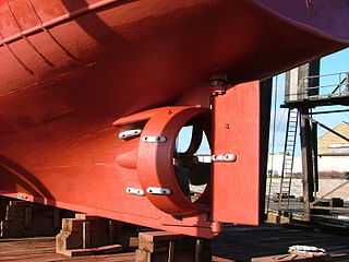
A ducted propeller, also known as a Kort nozzle, is a marine propeller fitted with a non-rotating nozzle. It is used to improve the efficiency of the propeller and is especially used on heavily loaded propellers or propellers with limited diameter. It was developed first by Luigi Stipa (1931) and later by Ludwig Kort (1934). The Kort nozzle is a shrouded propeller assembly for marine propulsion. The cross-section of the shroud has the form of a foil, and the shroud can offer hydrodynamic advantages over bare propellers, under certain conditions.

In aeronautics and marine hydrodynamics, the advance ratio is the ratio of the freestream fluid speed to the propeller, rotor, or cyclorotor tip speed. When a propeller-driven vehicle is moving at high speed relative to the fluid, or the propeller is rotating slowly, the advance ratio of its propeller(s) is a high number. When the vehicle is moving at low speed or the propeller is rotating at high speed, the advance ratio is a low number. The advance ratio is a useful non-dimensional quantity in helicopter and propeller theory, since propellers and rotors will experience the same angle of attack on every blade airfoil section at the same advance ratio regardless of actual forward speed. It is the inverse of the tip speed ratio used for wind turbines.
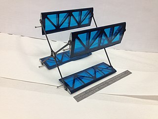
A cyclorotor, cycloidal rotor, cycloidal propeller or cyclogiro, is a fluid propulsion device that converts shaft power into the acceleration of a fluid using a rotating axis perpendicular to the direction of fluid motion. It uses several blades with a spanwise axis parallel to the axis of rotation and perpendicular to the direction of fluid motion. These blades are cyclically pitched twice per revolution to produce force in any direction normal to the axis of rotation. Cyclorotors are used for propulsion, lift, and control on air and water vehicles. An aircraft using cyclorotors as the primary source of lift, propulsion, and control is known as a cyclogyro or cyclocopter. A unique aspect is that it can change the magnitude and direction of thrust without the need of tilting any aircraft structures. The patented application, used on ships with particular actuation mechanisms both mechanical or hydraulic, is named after German company Voith Turbo.
Propeller theory is the science governing the design of efficient propellers. A propeller is the most common propulsor on ships, and on small aircraft.
Robert Edmund Froude CB FRS was an English engineer, hydrodynamicist and naval architect who described momentum theory, both used in the systematic evaluation of propeller design efficiency and as components of blade element momentum theory.
