Steady flight

Last updated
Forces acting on an airplane in steady level longitudinal flight, also known as straight and level flight, with a very small angle of attack. In steady level longitudinal flight, thrust counterbalances drag and lift supports the aircraft's weight. Lift and drag are components of the aerodynamic force. Steady flight.png
Forces acting on an airplane in steady level longitudinal flight, also known as straight and level flight, with a very small angle of attack. In steady level longitudinal flight, thrust counterbalances drag and lift supports the aircraft's weight. Lift and drag are components of the aerodynamic force.

Steady flight, unaccelerated flight, or equilibrium flight is a special case in flight dynamics where the aircraft's linear and angular velocity are constant in a body-fixed reference frame. [1] Basic aircraft maneuvers such as level flight, climbs and descents, and coordinated turns can be modeled as steady flight maneuvers. [2] Typical aircraft flight consists of a series of steady flight maneuvers connected by brief, accelerated transitions. [3] Because of this, primary applications of steady flight models include aircraft design, assessment of aircraft performance, flight planning, and using steady flight states as the equilibrium conditions around which flight dynamics equations are expanded.

Contents

Reference frames

Steady flight analysis uses three different reference frames to express the forces and moments acting on the aircraft. They are defined as:

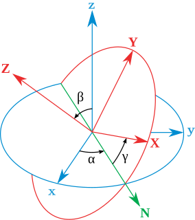
The Euler angles linking these reference frames are:

Force balance and the steady flight equations

The forces acting on an aircraft in flight are the weight, aerodynamic force, and thrust. [4] The weight is easiest to express in the Earth frame, where it has magnitude W and is in the +zE direction, towards the center of the Earth. The weight is assumed to be constant over time and constant with altitude.

Expressing the aerodynamic force in the wind frame, it has a drag component with magnitude D opposite the velocity vector in the −xw direction, a side force component with magnitude C in the +yw direction, and a lift component with magnitude L in the −zw direction.

In general, the thrust can have components along each body frame axis. For fixed wing aircraft with engines or propellers fixed relative to the fuselage, thrust is usually closely aligned with the +xb direction. Other types of aircraft, such as rockets and airplanes that use thrust vectoring, can have significant components of thrust along the other body frame axes. [4] In this article, aircraft are assumed to have thrust with magnitude T and fixed direction +xb.

Steady flight is defined as flight where the aircraft's linear and angular velocity vectors are constant in a body-fixed reference frame such as the body frame or wind frame. [1] In the Earth frame, the velocity may not be constant since the airplane may be turning, in which case the airplane has a centripetal acceleration in the xE-yE plane, where is the magnitude of the true airspeed and is the turn radius.

This equilibrium can be expressed along a variety of axes in a variety of reference frames. The traditional steady flight equations derive from expressing this force balance along three axes: the xw-axis, the radial direction of the aircraft's turn in the xE-yE plane, and the axis perpendicular to xw in the xw-zE plane, [5]

where g is the standard acceleration due to gravity.

These equations can be simplified with several assumptions that are typical of simple, fixed-wing flight. First, assume that the sideslip β is zero, or coordinated flight. Second, assume the side force C is zero. Third, assume that the angle of attack α is small enough that cos(α)≈1 and sin(α)≈α, which is typical since airplanes stall at high angles of attack. Similarly, assume that the flight-path angle γ is small enough that cos(γ)≈1 and sin(γ)≈γ, or equivalently that climbs and descents are at small angles relative to horizontal. Finally, assume that thrust is much smaller than lift, TL. Under these assumptions, the equations above simplify to [5]

These equations show that the thrust must be sufficiently large to cancel drag and the longitudinal component of weight. They also show that the lift must be sufficiently large to support the aircraft weight and accelerate the aircraft through turns.

Dividing the second equation by the third equation and solving for R shows that the turn radius can be written in terms of the true airspeed and the bank angle,

The constant angular velocity in the body frame leads to a balance of moments, as well. Most notably, the pitching moment being zero puts a constraint on the longitudinal motion of the aircraft that can be used to determine the elevator control input.

Force balance in straight and level flight

In steady level longitudinal flight, also known as straight and level flight, the aircraft holds a constant heading, airspeed, and altitude. In this case, the flight-path angle γ = 0, the bank angle μ = 0, and the turn radius becomes infinitely large since the airplane is not turning. For steady level longitudinal flight, the steady flight equations simplify to

So, in this particular steady flight maneuver thrust counterbalances drag while lift supports the aircraft's weight. This force balance is pictured in the graphic at the beginning of the article.

Steady flight maneuvers

The most general maneuver described by the steady flight equations above is a steady climbing or descending coordinated turn. The trajectory the aircraft flies during this maneuver is a helix with zE as its axis and a circular projection on the xE-yE plane. [6] Other steady flight maneuvers are special cases of this helical trajectory.

The definition of steady flight also allows for other maneuvers that are steady only instantaneously if the control inputs are held constant. These include the steady roll, where there is a constant and non-zero roll rate, and the steady pull up, where there is a constant but non-zero pitch rate.

See also

Notes

Related Research Articles

Polar coordinate system Coordinates determined by distance and angle

In mathematics, the polar coordinate system is a two-dimensional coordinate system in which each point on a plane is determined by a distance from a reference point and an angle from a reference direction. The reference point is called the pole, and the ray from the pole in the reference direction is the polar axis. The distance from the pole is called the radial coordinate, radial distance or simply radius, and the angle is called the angular coordinate, polar angle, or azimuth. Angles in polar notation are generally expressed in either degrees or radians.

Rotation Movement of an object around an axis

Rotation is the circular movement of an object around an axis of rotation. A three-dimensional object may have an infinite number of rotation axes.

In physics, angular velocity or rotational velocity, also known as angular frequency vector, is a vector measure of rotation rate, that refers to how fast an object rotates or revolves relative to another point, i.e. how fast the angular position or orientation of an object changes with time.

Biot–Savart law Important law of classical magnetism

In physics, specifically electromagnetism, the Biot–Savart law is an equation describing the magnetic field generated by a constant electric current. It relates the magnetic field to the magnitude, direction, length, and proximity of the electric current. The Biot–Savart law is fundamental to magnetostatics, playing a role similar to that of Coulomb's law in electrostatics. When magnetostatics does not apply, the Biot–Savart law should be replaced by Jefimenko's equations. The law is valid in the magnetostatic approximation, and consistent with both Ampère's circuital law and Gauss's law for magnetism. It is named after Jean-Baptiste Biot and Félix Savart, who discovered this relationship in 1820.

Transverse wave Moving wave whose oscillations are perpendicular to the direction of the wave

In physics, a transverse wave is a wave whose oscillations are perpendicular to the direction of the wave's advance. This is in contrast to a longitudinal wave which travels in the direction of its oscillations.

Orbital mechanics Field of classical mechanics concerned with the motion of spacecraft

Orbital mechanics or astrodynamics is the application of ballistics and celestial mechanics to the practical problems concerning the motion of rockets and other spacecraft. The motion of these objects is usually calculated from Newton's laws of motion and law of universal gravitation. Orbital mechanics is a core discipline within space-mission design and control.

Flight dynamics (fixed-wing aircraft) Science of air vehicle orientation and control in three dimensions

Flight dynamics is the science of air vehicle orientation and control in three dimensions. The three critical flight dynamics parameters are the angles of rotation in three dimensions about the vehicle's center of gravity (cg), known as pitch, roll and yaw.

Euler angles Description of the orientation of a rigid body

The Euler angles are three angles introduced by Leonhard Euler to describe the orientation of a rigid body with respect to a fixed coordinate system.

A nonholonomic system in physics and mathematics is a physical system whose state depends on the path taken in order to achieve it. Such a system is described by a set of parameters subject to differential constraints, such that when the system evolves along a path in its parameter space but finally returns to the original set of parameter values at the start of the path, the system itself may not have returned to its original state.

Projectile motion Motion of launched objects due to gravity

Projectile motion is a form of motion experienced by an object or particle that is projected near the Earth's surface and moves along a curved path under the action of gravity only. This curved path was shown by Galileo to be a parabola, but may also be a line in the special case when it is thrown directly upwards. The study of such motions is called ballistics, and such a trajectory is a ballistic trajectory. The only force of mathematical significance that is actively exerted on the object is gravity, which acts downward, thus imparting to the object a downward acceleration towards the Earth’s center of mass. Because of the object's inertia, no external force is needed to maintain the horizontal velocity component of the object's motion. Taking other forces into account, such as aerodynamic drag or internal propulsion, requires additional analysis. A ballistic missile is a missile only guided during the relatively brief initial powered phase of flight, and whose remaining course is governed by the laws of classical mechanics.

The rigid rotor is a mechanical model of rotating systems. An arbitrary rigid rotor is a 3-dimensional rigid object, such as a top. To orient such an object in space requires three angles, known as Euler angles. A special rigid rotor is the linear rotor requiring only two angles to describe, for example of a diatomic molecule. More general molecules are 3-dimensional, such as water, ammonia, or methane.

Flight dynamics (spacecraft) Application of mechanical dynamics to model the flight of space vehicles

Spacecraft flight dynamics is the application of mechanical dynamics to model how the external forces acting on a space vehicle or spacecraft determine its flight path. These forces are primarily of three types: propulsive force provided by the vehicle's engines; gravitational force exerted by the Earth and other celestial bodies; and aerodynamic lift and drag.

A banked turn is a turn or change of direction in which the vehicle banks or inclines, usually towards the inside of the turn. For a road or railroad this is usually due to the roadbed having a transverse down-slope towards the inside of the curve. The bank angle is the angle at which the vehicle is inclined about its longitudinal axis with respect to the horizontal.

Theoretical motivation for general relativity

A theoretical motivation for general relativity, including the motivation for the geodesic equation and the Einstein field equation, can be obtained from special relativity by examining the dynamics of particles in circular orbits about the earth. A key advantage in examining circular orbits is that it is possible to know the solution of the Einstein Field Equation a priori. This provides a means to inform and verify the formalism.

Stability derivatives

Stability derivatives, and also control derivatives, are measures of how particular forces and moments on an aircraft change as other parameters related to stability change. For a defined "trim" flight condition, changes and oscillations occur in these parameters. Equations of motion are used to analyze these changes and oscillations. Stability and control derivatives are used to linearize (simplify) these equations of motion so the stability of the vehicle can be more readily analyzed.

Law of cosines Property of all triangles on a Euclidean plane

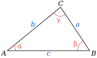
In trigonometry, the law of cosines relates the lengths of the sides of a triangle to the cosine of one of its angles. Using notation as in Fig. 1, the law of cosines states

In celestial mechanics, Lambert's problem is concerned with the determination of an orbit from two position vectors and the time of flight, posed in the 18th century by Johann Heinrich Lambert and formally solved with mathematical proof by Joseph-Louis Lagrange. It has important applications in the areas of rendezvous, targeting, guidance, and preliminary orbit determination.

Side looking airborne radar

Side-looking airborne radar (SLAR) is an aircraft- or satellite-mounted imaging radar pointing perpendicular to the direction of flight. A squinted (nonperpendicular) mode is possible also. SLAR can be fitted with a standard antenna or an antenna using synthetic aperture.

In optics, polarization mixing refers to changes in the relative strengths of the Stokes parameters caused by reflection or scattering—see vector radiative transfer—or by changes in the radial orientation of the detector.

In physics and engineering, Davenport chained rotations are three chained intrinsic rotations about body-fixed specific axes. Euler rotations and Tait–Bryan rotations are particular cases of the Davenport general rotation decomposition. The angles of rotation are called Davenport angles because the general problem of decomposing a rotation in a sequence of three was studied first by Paul B. Davenport.

References