Related Research Articles
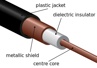
A transmission medium is a system or substance that can mediate the propagation of signals for the purposes of telecommunication. Signals are typically imposed on a wave of some kind suitable for the chosen medium. For example, data can modulate sound, and a transmission medium for sounds may be air, but solids and liquids may also act as the transmission medium. Vacuum or air constitutes a good transmission medium for electromagnetic waves such as light and radio waves. While material substance is not required for electromagnetic waves to propagate, such waves are usually affected by the transmission media they pass through, for instance, by absorption or reflection or refraction at the interfaces between media. Technical devices can therefore be employed to transmit or guide waves. Thus, an optical fiber or a copper cable is used as transmission media.

Very high frequency (VHF) is the ITU designation for the range of radio frequency electromagnetic waves from 30 to 300 megahertz (MHz), with corresponding wavelengths of ten meters to one meter. Frequencies immediately below VHF are denoted high frequency (HF), and the next higher frequencies are known as ultra high frequency (UHF).

Radio waves are a type of electromagnetic radiation with the longest wavelengths in the electromagnetic spectrum, typically with frequencies of 300 gigahertz (GHz) and below. At 300 GHz, the corresponding wavelength is 1 mm ; at 30 Hz the corresponding wavelength is 10,000 kilometers. Like all electromagnetic waves, radio waves in a vacuum travel at the speed of light, and in the Earth's atmosphere at a close, but slightly lower speed. Radio waves are generated by charged particles undergoing acceleration, such as time-varying electric currents. Naturally occurring radio waves are emitted by lightning and astronomical objects, and are part of the blackbody radiation emitted by all warm objects.

Radio navigation or radionavigation is the application of radio frequencies to determine a position of an object on the Earth, either the vessel or an obstruction. Like radiolocation, it is a type of radiodetermination.
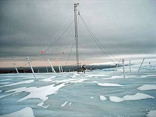
Very low frequency or VLF is the ITU designation for radio frequencies (RF) in the range of 3–30 kHz, corresponding to wavelengths from 100 to 10 km, respectively. The band is also known as the myriameter band or myriameter wave as the wavelengths range from one to ten myriameters. Due to its limited bandwidth, audio (voice) transmission is highly impractical in this band, and therefore only low data rate coded signals are used. The VLF band is used for a few radio navigation services, government time radio stations and for secure military communication. Since VLF waves can penetrate at least 40 meters (131 ft) into saltwater, they are used for military communication with submarines.
Low frequency (LF) is the ITU designation for radio frequencies (RF) in the range of 30–300 kHz. Since its wavelengths range from 10–1 km, respectively, it is also known as the kilometre band or kilometre wave.

Medium frequency (MF) is the ITU designation for radio frequencies (RF) in the range of 300 kilohertz (kHz) to 3 megahertz (MHz). Part of this band is the medium wave (MW) AM broadcast band. The MF band is also known as the hectometer band as the wavelengths range from ten to one hectometer. Frequencies immediately below MF are denoted low frequency (LF), while the first band of higher frequencies is known as high frequency (HF). MF is mostly used for AM radio broadcasting, navigational radio beacons, maritime ship-to-shore communication, and transoceanic air traffic control.

A radio clock or radio-controlled clock (RCC), and often (incorrectly) referred to as an atomic clock is a type of quartz clock or watch that is automatically synchronized to a time code transmitted by a radio transmitter connected to a time standard such as an atomic clock. Such a clock may be synchronized to the time sent by a single transmitter, such as many national or regional time transmitters, or may use the multiple transmitters used by satellite navigation systems such as Global Positioning System. Such systems may be used to automatically set clocks or for any purpose where accurate time is needed. RC clocks may include any feature available for a clock, such as alarm function, display of ambient temperature and humidity, broadcast radio reception, etc.

In radio, longwave, long wave or long-wave, and commonly abbreviated LW, refers to parts of the radio spectrum with wavelengths longer than what was originally called the medium-wave broadcasting band. The term is historic, dating from the early 20th century, when the radio spectrum was considered to consist of longwave (LW), medium-wave (MW), and short-wave (SW) radio bands. Most modern radio systems and devices use wavelengths which would then have been considered 'ultra-short'.
Radio propagation is the behavior of radio waves as they travel, or are propagated, from one point to another in vacuum, or into various parts of the atmosphere. As a form of electromagnetic radiation, like light waves, radio waves are affected by the phenomena of reflection, refraction, diffraction, absorption, polarization, and scattering. Understanding the effects of varying conditions on radio propagation has many practical applications, from choosing frequencies for amateur radio communications, international shortwave broadcasters, to designing reliable mobile telephone systems, to radio navigation, to operation of radar systems.

A non-directional beacon (NDB) or non-directional radio beacon is a radio beacon which does not include inherent directional information. Radio beacons are radio transmitters at a known location, used as an aviation or marine navigational aid. NDB are in contrast to directional radio beacons and other navigational aids, such as low-frequency radio range, VHF omnidirectional range (VOR) and tactical air navigation system (TACAN).

Direction finding (DF), or radio direction finding (RDF), is – in accordance with International Telecommunication Union (ITU) – defined as radio location that uses the reception of radio waves to determine the direction in which a radio station or an object is located. This can refer to radio or other forms of wireless communication, including radar signals detection and monitoring (ELINT/ESM). By combining the direction information from two or more suitably spaced receivers, the source of a transmission may be located via triangulation. Radio direction finding is used in the navigation of ships and aircraft, to locate emergency transmitters for search and rescue, for tracking wildlife, and to locate illegal or interfering transmitters. RDF was important in combating German threats during both the World War II Battle of Britain and the long running Battle of the Atlantic. In the former, the Air Ministry also used RDF to locate its own fighter groups and vector them to detected German raids.
Radiolocation, also known as radiolocating or radiopositioning, is the process of finding the location of something through the use of radio waves. It generally refers to passive uses, particularly radar—as well as detecting buried cables, water mains, and other public utilities. It is similar to radionavigation, but radiolocation usually refers to passively finding a distant object rather than actively one's own position. Both are types of radiodetermination. Radiolocation is also used in real-time locating systems (RTLS) for tracking valuable assets.
A link budget is an accounting of all of the power gains and losses that a communication signal experiences in a telecommunication system; from a transmitter, through a communication medium such as radio waves, cable, waveguide, or optical fiber, to the receiver. It is an equation giving the received power from the transmitter power, after the attenuation of the transmitted signal due to propagation, as well as the antenna gains and feedline and other losses, and amplification of the signal in the receiver or any repeaters it passes through. A link budget is a design aid, calculated during the design of a communication system to determine the received power, to ensure that the information is received intelligibly with an adequate signal-to-noise ratio. Randomly varying channel gains such as fading are taken into account by adding some margin depending on the anticipated severity of its effects. The amount of margin required can be reduced by the use of mitigating techniques such as antenna diversity or frequency hopping.
Multilateration is a technique for determining a "vehicle's" position based on measurement of the times of arrival (TOAs) of energy waves traveling from (navigation) or to (surveillance) multiple system stations having synchronized "clocks". Multilateration is: abbreviated MLAT; more completely termed pseudo-range multilateration; and also termed hyperbolic positioning.
A positioning system is a system for determining the position of an object in space. One of the most well-known and commonly used positioning systems is the Global Positioning System (GPS).

In navigation, a radio beacon or radiobeacon is a kind of beacon, a device that marks a fixed location and allows direction-finding equipment to find relative bearing. But instead of employing visible light, radio beacons transmit electromagnetic radiation in the radio wave band. They are used for direction-finding systems on ships, aircraft and vehicles.

An indoor positioning system (IPS) is a network of devices used to locate people or objects where GPS and other satellite technologies lack precision or fail entirely, such as inside multistory buildings, airports, alleys, parking garages, and underground locations.

Radio is the technology of signaling and communicating using radio waves. Radio waves are electromagnetic waves of frequency between 30 hertz (Hz) and 300 gigahertz (GHz). They are generated by an electronic device called a transmitter connected to an antenna which radiates the waves, and received by another antenna connected to a radio receiver. Radio is very widely used in modern technology, in radio communication, radar, radio navigation, remote control, remote sensing, and other applications.

A Bellini–Tosi direction finder is a type of radio direction finder (RDF), which determines the direction to, or bearing of, a radio transmitter. Earlier RDF systems used very large rotating loop antennae, which the B–T system replaced with two fixed antennae and a small rotating loop, known as a radiogoniometer. This made RDF much more practical, especially on large vehicles like ships or when using very long wavelengths that demand large antennae.
References
- R.P. Loweth (1997). Manual of Offshore Surveying for Geoscientists and Engineers (1st ed.). Chapman & Hall. p. 115. ISBN 0-412-80550-2. LCCN 96-72156.
- Wireless World. Vol. 89. Dorset House. 1983. p. 73.
| | This article related to radio communications is a stub. You can help Wikipedia by expanding it. |