
An operational amplifier is a DC-coupled electronic voltage amplifier with a differential input, a (usually) single-ended output, and an extremely high gain. Its name comes from its original use of performing mathematical operations in analog computers.

In electrical engineering, a transformer is a passive component that transfers electrical energy from one electrical circuit to another circuit, or multiple circuits. A varying current in any coil of the transformer produces a varying magnetic flux in the transformer's core, which induces a varying electromotive force (EMF) across any other coils wound around the same core. Electrical energy can be transferred between separate coils without a metallic (conductive) connection between the two circuits. Faraday's law of induction, discovered in 1831, describes the induced voltage effect in any coil due to a changing magnetic flux encircled by the coil.

An electric motor is a machine that converts electrical energy into mechanical energy. Most electric motors operate through the interaction between the motor's magnetic field and electric current in a wire winding to generate force in the form of torque applied on the motor's shaft. An electric generator is mechanically identical to an electric motor, but operates in reverse, converting mechanical energy into electrical energy.
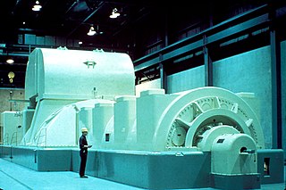
In electricity generation, a generator is a device that converts motion-based power or fuel-based power into electric power for use in an external circuit. Sources of mechanical energy include steam turbines, gas turbines, water turbines, internal combustion engines, wind turbines and even hand cranks. The first electromagnetic generator, the Faraday disk, was invented in 1831 by British scientist Michael Faraday. Generators provide nearly all the power for electrical grids.

In electronics, negative resistance (NR) is a property of some electrical circuits and devices in which an increase in voltage across the device's terminals results in a decrease in electric current through it.

In an audio system, the damping factor is defined as the ratio of the rated impedance of the loudspeaker to the source impedance of the power amplifier. It was originally proposed in 1941. Only the magnitude of the loudspeaker impedance is used, and the power amplifier output impedance is assumed to be totally resistive.

In electrical engineering, the output impedance of an electrical network is the measure of the opposition to current flow (impedance), both static (resistance) and dynamic (reactance), into the load network being connected that is internal to the electrical source. The output impedance is a measure of the source's propensity to drop in voltage when the load draws current, the source network being the portion of the network that transmits and the load network being the portion of the network that consumes.
In electrical engineering and electronics, a network is a collection of interconnected components. Network analysis is the process of finding the voltages across, and the currents through, all network components. There are many techniques for calculating these values; however, for the most part, the techniques assume linear components. Except where stated, the methods described in this article are applicable only to linear network analysis.

A current source is an electronic circuit that delivers or absorbs an electric current which is independent of the voltage across it.

A pulse-forming network (PFN) is an electric circuit that accumulates electrical energy over a comparatively long time, and then releases the stored energy in the form of a relatively square pulse of comparatively brief duration for various pulsed power applications. In a PFN, energy storage components such as capacitors, inductors or transmission lines are charged by means of a high-voltage power source, then rapidly discharged into a load through a high-voltage switch, such as a spark gap or hydrogen thyratron. Repetition rates range from single pulses to about 104 per second. PFNs are used to produce uniform electrical pulses of short duration to power devices such as klystron or magnetron tube oscillators in radar sets, pulsed lasers, particle accelerators, flashtubes, and high-voltage utility test equipment.
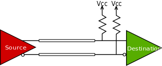
Current mode logic (CML), or source-coupled logic (SCL), is a digital design style used both for logic gates and for board-level digital signaling of digital data.

Seen in some magnetic materials, saturation is the state reached when an increase in applied external magnetic field H cannot increase the magnetization of the material further, so the total magnetic flux density B more or less levels off. Saturation is a characteristic of ferromagnetic and ferrimagnetic materials, such as iron, nickel, cobalt and their alloys. Different ferromagnetic materials have different saturation levels.
The chief electrical characteristic of a dynamic loudspeaker's driver is its electrical impedance as a function of frequency. It can be visualized by plotting it as a graph, called the impedance curve.
Islanding is the intentional or unintentional division of an interconnected power grid into individual disconnected regions with their own power generation.

A signal travelling along an electrical transmission line will be partly, or wholly, reflected back in the opposite direction when the travelling signal encounters a discontinuity in the characteristic impedance of the line, or if the far end of the line is not terminated in its characteristic impedance. This can happen, for instance, if two lengths of dissimilar transmission lines are joined.
In a synchronous generator, the short circuit ratio is the ratio of field current required to produce rated armature voltage at the open circuit to the field current required to produce the rated armature current at short circuit. This ratio can also be expressed as an inverse of the saturated direct-axis synchronous reactance :
The reactances of synchronous machines comprise a set of characteristic constants used in the theory of synchronous machines. Technically, these constants are specified in units of the electrical reactance (ohms), although they are typically expressed in the per-unit system and thus dimensionless. Since for practically all machines the resistance of the coils is negligibly small in comparison to the reactance, the latter can be used instead of (complex) electrical impedance, simplifying the calculations.

The open-circuit saturation curve of a synchronous generator is a plot of the output open circuit voltage as a function of the excitation current or field. The curve is typically plotted alongside the synchronous impedance curve.

Air gap in magnetic circuits is a term used to define an intentional gap left in the magnetic material.
The zero power factor curve of a synchronous generator is a plot of the output voltage as a function of the excitation current or field using a zero power factor load that corresponds to rated voltage at rated current. The curve is typically plotted alongside the open-circuit characteristic.


