Thyristor controlled reactor

Last updated

In an electric power transmission system, a thyristor-controlled reactor (TCR) is a reactance connected in series with a bidirectional thyristor valve. The thyristor valve is phase-controlled, which allows the value of delivered reactive power to be adjusted to meet varying system conditions. Thyristor-controlled reactors can be used for limiting voltage rises on lightly loaded transmission lines. Another device which used to be used for this purpose is a magnetically controlled reactor (MCR), a type of magnetic amplifier otherwise known as a transductor.

Electrical grid Interconnected network for delivering electricity from suppliers to consumers

An electrical grid', or electric grid, is an interconnected network for delivering electricity from producers to consumers. It consists of

Thyristor semiconductor device with three or more p-n junctions, having two steady states: off (non-conducting) and on (conducting)

A thyristor is a solid-state semiconductor device with four layers of alternating P- and N-type materials. It acts exclusively as a bistable switch, conducting when the gate receives a current trigger, and continuing to conduct until the voltage across the device is reversed biased, or until the voltage is removed. A three-lead thyristor is designed to control the larger current of the Anode to Cathode path by controlling that current with the smaller current of its other lead, known as its Gate. In contrast, a two-lead thyristor is designed to switch on if the potential difference between its leads is sufficiently large.

The magnetic amplifier is an electromagnetic device for amplifying electrical signals. The magnetic amplifier was invented early in the 20th century, and was used as an alternative to vacuum tube amplifiers where robustness and high current capacity were required. World War II Germany perfected this type of amplifier, and it was used in the V-2 rocket. The magnetic amplifier was most prominent in power control and low-frequency signal applications from 1947 to about 1957, when the transistor began to supplant it. The magnetic amplifier has now been largely superseded by the transistor-based amplifier, except in a few safety critical, high-reliability or extremely demanding applications. Combinations of transistor and mag-amp techniques are still used.

Contents

In parallel with series connected reactance and thyristor valve, there may also be a capacitor bank, which may be permanently connected or which may use mechanical or thyristor switching. The combination is called a static VAR compensator.

A static VAR compensator is a set of electrical devices for providing fast-acting reactive power on high-voltage electricity transmission networks. SVCs are part of the Flexible AC transmission system device family, regulating voltage, power factor, harmonics and stabilizing the system. A static VAR compensator has no significant moving parts. Prior to the invention of the SVC, power factor compensation was the preserve of large rotating machines such as synchronous condensers or switched capacitor banks.

Circuit diagram

A thyristor controlled reactor is usually a three-phase assembly, normally connected in a delta arrangement to provide partial cancellation of Harmonics. Often the main TCR reactor is split into two halves, with the thyristor valve connected between the two halves. This protects the vulnerable thyristor valve from damage due to flashovers, lightning strikes etc.

Harmonic

A harmonic is any member of the harmonic series. The term is employed in various disciplines, including music, physics, acoustics, electronic power transmission, radio technology, and other fields. It is typically applied to repeating signals, such as sinusoidal waves. A harmonic of such a wave is a wave with a frequency that is a positive integer multiple of the frequency of the original wave, known as the fundamental frequency. The original wave is also called the 1st harmonic, the following harmonics are known as higher harmonics. As all harmonics are periodic at the fundamental frequency, the sum of harmonics is also periodic at that frequency. For example, if the fundamental frequency is 50 Hz, a common AC power supply frequency, the frequencies of the first three higher harmonics are 100 Hz, 150 Hz, 200 Hz and any addition of waves with these frequencies is periodic at 50 Hz.

An nth characteristic mode, for n > 1, will have nodes that are not vibrating. For example, the 3rd characteristic mode will have nodes at L and L, where L is the length of the string. In fact, each nth characteristic mode, for n not a multiple of 3, will not have nodes at these points. These other characteristic modes will be vibrating at the positions L and L. If the player gently touches one of these positions, then these other characteristic modes will be suppressed. The tonal harmonics from these other characteristic modes will then also be suppressed. Consequently, the tonal harmonics from the nth characteristic modes, where n is a multiple of 3, will be made relatively more prominent.

Thyristor Controlled Reactor circuit.png

Operating principles

The current in the TCR is varied from maximum (determined by the connection voltage and the inductance of the reactor) to almost zero by varying the "Firing Delay Angle", α. α is defined as the delay angle from the point at which the voltage becomes positive to the point at which the thyristor valve is turned on and current starts to flow.

Voltage and current waveforms in a TCR Thyristor Controlled Reactor waveforms.png
Voltage and current waveforms in a TCR

Maximum current is obtained when α is 90°, at which point the TCR is said to be in "full conduction" and the rms current is given by:

Where:

Vsvc is the rms value of the line-to-line busbar voltage to which the SVC is connected

Ltcr is the total TCR inductance per phase

The current lags 90° behind the voltage in accordance with classical AC circuit theory. As α increases above 90°, up to a maximum of 180°, the current decreases and becomes discontinuous and non-sinusoidal. The TCR current, as a function of time, is then given by:

Otherwise, zero.

Main equipment

A TCR comprises two main items of equipment: the reactor itself, which is usually air-cored (although iron-cored reactors are possible) and the thyristor valve. Depending on the system voltage, an intermediate power transformer may be required to step up from the voltage handled by the thyristors to the transmission system voltage.

Transformer electrical artefact that transfers energy through electromagnetic induction

A transformer is a static electrical device that transfers electrical energy between two or more circuits. A varying current in one coil of the transformer produces a varying magnetic flux, which, in turn, induces a varying electromotive force across a second coil wound around the same core. Electrical energy can be transferred between the two coils, without a metallic connection between the two circuits. Faraday's law of induction discovered in 1831 described the induced voltage effect in any coil due to changing magnetic flux encircled by the coil.

Thyristor valve

The thyristor valve typically consists of 5-20 inverse-parallel-connected pairs of Thyristors connected in series. The inverse-parallel connection is needed because most commercially available thyristors can conduct current in only one direction. The series connection is needed because the maximum voltage rating of commercially available thyristors (up to approximately 8.5 kV) is insufficient for the voltage at which the TCR is connected. For some low-voltage applications, it may be possible to avoid the series-connection of thyristors; in such cases the thyristor valve is simply an inverse-parallel connection of two thyristors.

A TCR Thyristor Valve (one phase) Thyristor Controlled Reactor Valve.png
A TCR Thyristor Valve (one phase)
TCR Thyristor valve voltage and current waveforms Thyristor Controlled Reactor valve waveforms.png
TCR Thyristor valve voltage and current waveforms

In addition to the thyristors themselves, each inverse-parallel pair of thyristors has a Resistor - Capacitor circuit connected across it, to force the voltage across the valve to divide uniformly amongst the thyristors and to damp the "commutation overshoot" which occurs when the valve turns off.

Resistor Passive electrical component providing electrical resistance

A resistor is a passive two-terminal electrical component that implements electrical resistance as a circuit element. In electronic circuits, resistors are used to reduce current flow, adjust signal levels, to divide voltages, bias active elements, and terminate transmission lines, among other uses. High-power resistors that can dissipate many watts of electrical power as heat, may be used as part of motor controls, in power distribution systems, or as test loads for generators. Fixed resistors have resistances that only change slightly with temperature, time or operating voltage. Variable resistors can be used to adjust circuit elements, or as sensing devices for heat, light, humidity, force, or chemical activity.

Capacitor electrical component used to store energy for a short period of time

A capacitor is a passive two-terminal electronic component that stores electrical energy in an electric field. The effect of a capacitor is known as capacitance. While some capacitance exists between any two electrical conductors in proximity in a circuit, a capacitor is a component designed to add capacitance to a circuit. The capacitor was originally known as a condenser or condensator. The original name is still widely used in many languages, but not commonly in English.

Harmonics

A TCR operating with α > 90° generates substantial amounts of harmonic currents, particularly at 3rd, 5th and 7th harmonics. By connecting the TCR in delta, the harmonic currents of order 3n ("Triplen harmonics") flow only around the delta and do not escape into the connected AC system. However, the 5th and 7th harmonics (and to a lesser extent 11th, 13th, 17th etc.) must be filtered in order to prevent excessive voltage distortion on the AC network. This is usually accomplished by connecting Harmonic Filters in parallel with the TCR. The filters provide capacitive reactive power which partly offsets the inductive reactive power provided by the TCR.

Related Research Articles

In mechanics and physics, simple harmonic motion is a special type of periodic motion or oscillation motion where the restoring force is directly proportional to the displacement and acts in the direction opposite to that of displacement.

Cutoff frequency frequency response boundary

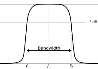
In physics and electrical engineering, a cutoff frequency, corner frequency, or break frequency is a boundary in a system's frequency response at which energy flowing through the system begins to be reduced rather than passing through.

The propagation constant of a sinusoidal electromagnetic wave is a measure of the change undergone by the amplitude and phase of the wave as it propagates in a given direction. The quantity being measured can be the voltage, the current in a circuit, or a field vector such as electric field strength or flux density. The propagation constant itself measures the change per unit length, but it is otherwise dimensionless. In the context of two-port networks and their cascades, propagation constant measures the change undergone by the source quantity as it propagates from one port to the next.

Electrical impedance intensive physical property

Electrical impedance is the measure of the opposition that a circuit presents to a current when a voltage is applied. The term complex impedance may be used interchangeably.

Rectifier AC-DC conversion device; electrical device that converts alternating current (AC), which periodically reverses direction, to direct current (DC), which flows in only one direction

A rectifier is an electrical device that converts alternating current (AC), which periodically reverses direction, to direct current (DC), which flows in only one direction.

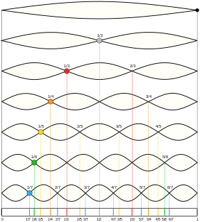
In physics, a phonon is a collective excitation in a periodic, elastic arrangement of atoms or molecules in condensed matter, like solids and some liquids. Often designated a quasiparticle, it represents an excited state in the quantum mechanical quantization of the modes of vibrations of elastic structures of interacting particles.

A flexible alternating current transmission system (FACTS) is a system composed of static equipment used for the AC transmission of electrical energy. It is meant to enhance controllability and increase power transfer capability of the network. It is generally a power electronics-based system.

In mathematics, the Hartley transform (HT) is an integral transform closely related to the Fourier transform (FT), but which transforms real-valued functions to real-valued functions. It was proposed as an alternative to the Fourier transform by Ralph V. L. Hartley in 1942, and is one of many known Fourier-related transforms. Compared to the Fourier transform, the Hartley transform has the advantages of transforming real functions to real functions and of being its own inverse.

LC circuit

An LC circuit, also called a resonant circuit, tank circuit, or tuned circuit, is an electric circuit consisting of an inductor, represented by the letter L, and a capacitor, represented by the letter C, connected together. The circuit can act as an electrical resonator, an electrical analogue of a tuning fork, storing energy oscillating at the circuit's resonant frequency.

The Havriliak–Negami relaxation is an empirical modification of the Debye relaxation model in electromagnetism. Unlike the Debye model, the Havriliak–Negami relaxation accounts for the asymmetry and broadness of the dielectric dispersion curve. The model was first used to describe the dielectric relaxation of some polymers, by adding two exponential parameters to the Debye equation:

In calculus, Leibniz's rule for differentiation under the integral sign, named after Gottfried Leibniz, states that for an integral of the form

Theoretical motivation for general relativity

A theoretical motivation for general relativity, including the motivation for the geodesic equation and the Einstein field equation, can be obtained from special relativity by examining the dynamics of particles in circular orbits about the earth. A key advantage in examining circular orbits is that it is possible to know the solution of the Einstein Field Equation a priori. This provides a means to inform and verify the formalism.

Ripple in electronics is the residual periodic variation of the DC voltage within a power supply which has been derived from an alternating current (AC) source. This ripple is due to incomplete suppression of the alternating waveform after rectification. Ripple voltage originates as the output of a rectifier or from generation and commutation of DC power.

The Cole–Cole equation is a relaxation model that is often used to describe dielectric relaxation in polymers.

The mathematics of pendulums are in general quite complicated. Simplifying assumptions can be made, which in the case of a simple pendulum allow the equations of motion to be solved analytically for small-angle oscillations.

In electrical engineering, the alpha-betatransformation is a mathematical transformation employed to simplify the analysis of three-phase circuits. Conceptually it is similar to the dq0 transformation. One very useful application of the transformation is the generation of the reference signal used for space vector modulation control of three-phase inverters.

An LC circuit can be quantized using the same methods as for the quantum harmonic oscillator. An LC circuit is a variety of resonant circuit, and consists of an inductor, represented by the letter L, and a capacitor, represented by the letter C. When connected together, an electric current can alternate between them at the circuit's resonant frequency:

RLC circuit

An RLC circuit is an electrical circuit consisting of a resistor (R), an inductor (L), and a capacitor (C), connected in series or in parallel. The name of the circuit is derived from the letters that are used to denote the constituent components of this circuit, where the sequence of the components may vary from RLC.

A thyristor switched capacitor (TSC) is a type of equipment used for compensating reactive power in electrical power systems. It consists of a power capacitor connected in series with a bidirectional thyristor valve and, usually, a current limiting reactor (inductor). The thyristor switched capacitor is an important component of a Static VAR Compensator (SVC), where it is often used in conjunction with a thyristor controlled reactor (TCR). Static VAR compensators are a member of the Flexible AC transmission system (FACTS) family.

Frequency selective surface

A frequency-selective surface (FSS) is any thin, repetitive surface designed to reflect, transmit or absorb electromagnetic fields based on the frequency of the field. In this sense, an FSS is a type of optical filter or metal-mesh optical filters in which the filtering is accomplished by virtue of the regular, periodic pattern on the surface of the FSS. Though not explicitly mentioned in the name, FSS's also have properties which vary with incidence angle and polarization as well - these are unavoidable consequences of the way in which FSS's are constructed. Frequency-selective surfaces have been most commonly used in the radio frequency region of the electromagnetic spectrum and find use in applications as diverse as the aforementioned microwave oven, antenna radomes and modern metamaterials. Sometimes frequency selective surfaces are referred to simply as periodic surfaces and are a 2-dimensional analog of the new periodic volumes known as photonic crystals.

References