Components of an electrical circuit are electrically connected if an electric current can run between them through an electrical conductor. An electrical connector is an electromechanical device used to create an electrical connection between parts of an electrical circuit, or between different electrical circuits, thereby joining them into a larger circuit. Most electrical connectors have a gender – i.e. the male component, called a plug, connects to the female component, or socket. The connection may be removable, require a tool for assembly and removal, or serve as a permanent electrical joint between two points. An adapter can be used to join dissimilar connectors.

A DC connector is an electrical connector for supplying direct current (DC) power.

A residual-current device (RCD), residual-current circuit breaker (RCCB) or ground fault circuit interrupter (GFCI) is an electrical safety device that quickly breaks an electrical circuit with leakage current to ground. It is to protect equipment and to reduce the risk of serious harm from an ongoing electric shock. Injury may still occur in some cases, for example if a human receives a brief shock before the electrical circuit is isolated, falls after receiving a shock, or if the person touches both conductors at the same time.
AC power plugs and sockets connect electric equipment to the alternating current (AC) mains electricity power supply in buildings and at other sites. Electrical plugs and sockets differ from one another in voltage and current rating, shape, size, and connector type. Different standard systems of plugs and sockets are used around the world.

A telephone jack and a telephone plug are electrical connectors for connecting a telephone set or other telecommunications apparatus to the telephone wiring inside a building, establishing a connection to a telephone network. The plug is inserted into its counterpart, the jack, which is commonly affixed to a wall or baseboard. The standards for telephone jacks and plugs vary from country to country, though the 6P2C style modular plug has become by far the most common type.
In an electrical system, a ground loop or earth loop occurs when two points of a circuit are intended to have the same ground reference potential but instead have a different potential between them. This is typically caused when enough current is flowing in the connection between the two ground points to produce a voltage drop and cause two points to be at different potentials. Current may be produced in a circular ground connection by electromagnetic induction.

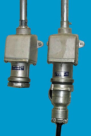
Industrial and multiphase plugs and sockets provide a connection to the electrical mains rated at higher voltages and currents than household plugs and sockets. They are generally used in polyphase systems, with high currents, or when protection from environmental hazards is required. Industrial outlets may have weatherproof covers, waterproofing sleeves, or may be interlocked with a switch to prevent accidental disconnection of an energized plug. Some types of connectors are approved for hazardous areas such as coal mines or petrochemical plants, where flammable gas may be present.
An earthing system or grounding system (US) connects specific parts of an electric power system with the ground, typically the Earth's conductive surface, for safety and functional purposes. The choice of earthing system can affect the safety and electromagnetic compatibility of the installation. Regulations for earthing systems vary among countries, though most follow the recommendations of the International Electrotechnical Commission (IEC). Regulations may identify special cases for earthing in mines, in patient care areas, or in hazardous areas of industrial plants.

NEMA connectors are power plugs and receptacles used for AC mains electricity in North America and other countries that use the standards set by the US National Electrical Manufacturers Association. NEMA wiring devices are made in current ratings from 15 to 60 amperes (A), with voltage ratings from 125 to 600 volts (V). Different combinations of contact blade widths, shapes, orientations, and dimensions create non-interchangeable connectors that are unique for each combination of voltage, electric current carrying capacity, and grounding system.

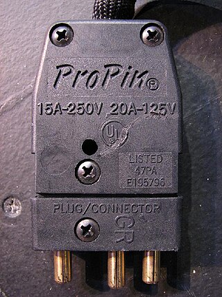
A stage pin connector, also known as a grounded stage pin (GSP) or grounded pin connector (GPC), is a standard cable type for theatrical lighting in North America and in many countries in the theatre world.

A modular connector is a type of electrical connector for cords and cables of electronic devices and appliances, such as in computer networking, telecommunication equipment, and audio headsets.

Towing is coupling two or more objects together so that they may be pulled by a designated power source or sources. The towing source may be a motorized land vehicle, vessel, animal, or human, and the load being anything that can be pulled. These may be joined by a chain, rope, bar, hitch, three-point, fifth wheel, coupling, drawbar, integrated platform, or other means of keeping the objects together while in motion.

Electrical or fiber-optic connectors used by U.S. Department of Defense were originally developed in the 1930s for severe aeronautical and tactical service applications, and the Type "AN" (Army-Navy) series set the standard for modern military circular connectors. These connectors, and their evolutionary derivatives, are often called Military Standard, "MIL-STD", or (informally) "MIL-SPEC" or sometimes "MS" connectors. They are now used in aerospace, industrial, marine, and even automotive commercial applications.

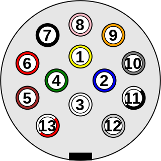
ISO 11446:2004 specifies a 13-pole electrical connector between towing and towed vehicles with 12 volt electrical system. It was developed in 1987 by Erich Jaeger to replace older 7-pin plugs.
A number of ISO standards cover trailer connectors, the electrical connectors between vehicles and the trailers they tow that provide a means of control for the trailers. These are listed below, with notes on significant deviations from them that can cause problems.
A number of standards prevail in North America, or parts of it, for trailer connectors, the electrical connectors between vehicles and the trailers they tow that provide a means of control for the trailers.
An electric friction brake, often referred to as just electric brake or electric trailer brake, is a brake controlled by an electric current and can be seen on medium duty trailers like caravans/RVs and consumer-grade car trailers. It is related to the electromagnetic track brake used in railways which also use electric current to directly control the brake force.

A number of standards prevail in Australia for trailer connectors, the electrical connectors between vehicles and the trailers they tow that provide a means of control trailer lamps, and in one case, trailer brakes, and also sometimes, manufacturer-specific non-standard functions.
A number of standards specific to military organizations exist for trailer connectors, the electrical connectors between vehicles and the trailers they tow that provide a means of control for the trailers. These can be found on surplus equipment sold for civilian use.

Plugs and sockets for electrical appliances not hardwired to mains electricity originated in the United Kingdom in the 1870s and were initially two-pin designs. These were usually sold as a mating pair, but gradually de facto and then official standards arose to enable the interchange of compatible devices. British standards have proliferated throughout large parts of the former British Empire.


