A number of ISO standards cover trailer connectors, the electrical connectors between vehicles and the trailers they tow that provide a means of control for the trailers. These are listed below, with notes on significant deviations from them that can cause problems.
In Europe, both 7-pin (ISO 1724) and 13-pin (ISO 11446) are common. The 13-pin version being phased in is newer, provides more services than the 7-pin, a more positive locking and also better protection against moisture and contamination.
The connectors are designed for 12V systems. Exceptions for the 7-pin connector may exist where they may be used for 6V and 24V.
Vehicles and trailers with 6V systems can use the 7-pin or a 5-pin connector, but these are rare today. Heavy trucks that may have 12V systems are usually older (vintage vehicles) or on non-European markets. [1]
The color coding is defined in ISO 4141-3, but the standard color codes are not always followed and may be different for a particular vehicle.
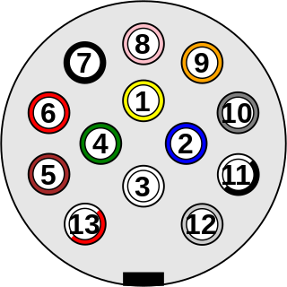
Physical design of the standard ISO 11446 [2] [3] but also called Jaeger-connector from the company that developed it.
# | DIN | Signal | Color | Rec. cross-section | Notes | |
---|---|---|---|---|---|---|
mm² | AWG | |||||
1 | L | Left turn signal | Yellow | 1.5 | 15 | |
2 | Rear fog lamps | Blue | 1.5 | 15 | ||
3 | 31 | Ground (-) for pin 1 - 8 | White | 2.5 | 13 | [ISO11446 1] |
4 | R | Right turn signal | Green | 1.5 | 15 | |
5 | 58R | Tail lamps, clearance lamps/outline marker lamps and registration plate lamp right side | Brown | 1.5 | 15 | [ISO11446 2] |
6 | 54 | Stop lamps | Red | 1.5 | 15 | |
7 | 58L | Tail lamps, clearance lamps/outline marker lamps and registration plate lamp left side | Black | 1.5 | 15 | [ISO11446 2] |
8 | Reversing lamps, control current to block surge brakes when reversing. | Pink | 1.5 | 15 | ||
9 | 30 | +12V permanent | Orange | 2.5 | 13 | |
10 | 15 | +12V via ignition lock | Grey | 2.5 | 13 | |
11 | 31 | Ground (-) for pin 10 | Black/White | 2.5 | 13 | [ISO11446 1] |
12 | Reserved for future allocation | Light Grey | 1.5 | 15 | [ISO11446 3] | |
13 | 31 | Ground (-) for pin 9 | Red/White | 2.5 | 13 | [ISO11446 1] |
The following supplementary information exists for the connector:
Other variants of this connector exists but they are rare. [5] One is used in 24V applications while the other is for ADR use. The difference is how they are mechanically keyed. These connectors are not very common.
Physical design according to standard ISO 7638-2. [4] [6] [7]
This connector is intended to be used for 12V ABS and EBS on heavy duty trailers.
Identified by key tab on outer ring between pin 3 and 4.
# | DIN | Signal | Color | Rec. cross-section | Notes | |
---|---|---|---|---|---|---|
mm² | AWG | |||||
1 | 30 | +12V permanent for control valves | Red | 4 | 11 | |
2 | 15 | +12V via ignition lock for electronics | Black | 1.5 | 15 | |
3 | 31 | Ground for electronics(Pin 2) | Yellow | 1.5 | 15 | |
4 | 31 | Ground for control valves (Pin 1) | Brown | 4 | 11 | |
5 | ABS Fault indication (Active low, i.e. when the voltage is below +5V) | White | 1.5 | 15 | [ISO7638-1 1] | |
6 | CAN H, For EBS and ABS | Green/White | 1.5 | 15 | [ISO7638-2 1] [ISO7638-2 2] | |
7 | CAN L, For EBS and ABS | Brown/White | 1.5 | 15 | [ISO7638-2 1] [ISO7638-2 2] | |
The following supplementary information exists for the connector:
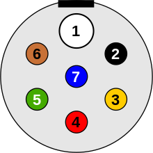
Physical design according to standard ISO 1724. [4] [8]
The 7-pin connector uses all 7 pins on newer trailers according to the ISO standard. [9] [10]
On older trailers there's sometimes a 5-wire setup using a 7-pin connector. In these cases exclude connection for right tail light (58R) and rear fog light (54G) and connect the tail lights only to pin for left tail light (58L). [11]
Joining the pins for right and left tail lights (58R and 58L) can cause problems on German cars where it is possible to activate Standing Lamps on only one side of the vehicle. [12]
# | DIN | Signal | Color | Rec. cross-section | Notes | |
---|---|---|---|---|---|---|
mm² | AWG | |||||
1 | L | Left turn signal | Yellow | 1.5 | 15 | |
2 | 54G | +12V from battery or Rear fog lights | Blue | 1.5 | 15 | |
3 | 31 | Ground connected to chassis | White or Grey | 2.5 | 13 | |
4 | R | Right turn signal | Green | 1.5 | 15 | |
5 | 58R | Tail lights, clearance lights/outline marker lights and registration plate light right side | Brown | 1.5 | 15 | |
6 | 54 | Stop lights | Red | 1.5 | 15 | |
7 | 58L | Tail lights, clearance lights/outline marker lights and registration plate light left side | Black | 1.5 | 15 | |
According to DIN 72552 pin 54G was initially intended for electrical control of brakes on trailers. [13]
Later pin 2 (54G) has been used for a variety of functions different from the original intent. A few examples:
This is why in regions using this connector, trailers on the road are occasionally seen with the rear fog lights on when they should be off. (Vehicle wired for +12V, permanent or via ignition and trailer wired for fog lamps)
Australia uses basically the same wiring with the exception for pin 5 and pin 2. The problematic part here is that pin 5 is used for trailer brake which means that if you for some reason connect an Australian trailer to a towing vehicle with ISO wiring you will get into trouble with the trailer brakes being applied as soon as you turn on the lights. [14]
Further reading at Trailer Connector/Australia.
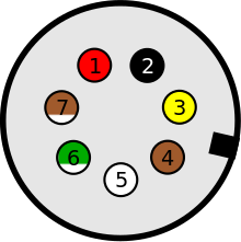
Physical design according to standard ISO 3732. [4] [15]
Signals in this connector (if following the standard) are not generally legally required (local regulations may still apply), which means that it is not mandatory to connect it if it is present.
This connector is basically the same as the 12N (ISO 1724) connector, but the center pin (pin 7) has changed gender to make the plug and outlet unique. Socket is replaced with pin in the plug, pin is replaced with socket in outlet.
The purpose of this connector is to supplement the 12N (ISO 1724) connector for power supply of consumers common in caravans (Travel trailers). [16] This is used in Great Britain but may also be used in other areas of Europe.
There are two main variants of the wiring with a switchover date 1999. The difference is that an additional connection for ground and that battery charging in the trailer is shared with other consumers. This means that if a pre-1999 camper trailer with a battery is connected to a post 1999 vehicle there's a risk that the battery charging won't work.
The combination of 12N+12S was replaced in 2008 by the 13-pin ISO 11446 connector.
# | DIN | British | ISO 3732 | Color | Rec. cross-section | Notes | |
---|---|---|---|---|---|---|---|
-1999 | 1999-2008 | mm² | AWG | ||||
1 | Reversing lamps | Reversing lamps | Yellow | 1.5 | 15 | ||
2 | (15) | Battery charging | Spare | Blue | 2.5 | 13 | [ISO3732 1] |
3 | 31 | Common ground | Common ground except for pin 6 | White or Grey | 2.5 | 13 | |
4 | 30 | Feed for internal 12V equipment except refrigerator | +12V permanent | Green | 2.5 | 13 | |
5 | Spare | Spare | Brown | 1.5 | 15 | ||
6 | 15 | Feed for refrigerator | +12V via ignition lock | Red | 2.5 | 13 | |
7 | Spare | ground for pin 6 | Black | 2.5 | 13 | ||
The following supplementary information exists for the connector:
Physical design according to standard ISO 1724. [4] [8]
The 5-pin has a design and pin layout that is identical to the 7-pin ISO 1724 connector with the exception for the lack of pin 1 (L) and pin 4 (R). This connector is sometimes present on vintage vehicles and the actual wiring may be completely different from what the standard states which means that measuring before connecting is a good idea.
Whenever there is a need to change the plug or outlet it can be replaced with a 7-pin.
These connectors are designated as 24 volt.
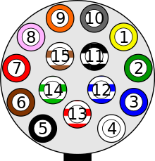
Physical design according to standard ISO 12098. [4] [17]
This connector is present on newer heavy duty commercial trucks and trailers following the ISO standard and is intended to replace the combination of connectors according to standards ISO 1185 and ISO 3731. The 15-pin connector is not designed to replace the ISO 7638 connector. [18]
# | DIN | Signal | Color | Rec. cross-section | Notes | |
---|---|---|---|---|---|---|
mm² | AWG | |||||
1 | L | Left turn signal | Yellow | 1.5 | 15 | |
2 | R | Right turn signal | Green | 1.5 | 15 | |
3 | Rear fog lamps | Blue | 1.5 | 15 | ||
4 | 31 | Ground (-) for pin 1 - 3 and 5 - 12 | White | 2.5 | 13 | |
5 | 58L | Tail lamps, clearance lamps/outline marker lamps, identification lamps and registration plate lamp left side | Black | 1.5 | 15 | [ISO12098 1] [ISO12098 2] |
6 | 58R | Tail lamps, clearance lamps/outline marker lamps, identification lamps and registration plate lamp right side | Brown | 1.5 | 15 | [ISO12098 1] [ISO12098 2] |
7 | 54 | Stop lamps | Red | 1.5 | 15 | |
8 | Reversing lamps | Pink | 1.5 | 15 | ||
9 | 30 | +24V permanent | Orange | 2.5 | 13 | |
10 | Brake wear indicator [19] | Grey | 1.5 | 15 | ||
11 | Indication of applied parking brake due to loss of air pressure | Black/White | 1.5 | 15 | ||
12 | Lift Axle | Blue/White | 1.5 | 15 | ||
13 | 31 | ground (-) for pin 14 and 15 | Red/White | 2.5 | 13 | |
14 | CAN H, Not for EBS or ABS | Green/White | 1.5 | 15 | [ISO12098 3] | |
15 | CAN L, Not for EBS or ABS | Brown/White | 1.5 | 15 | [ISO12098 3] | |
The following supplementary information exists for the connector:
Notice: There was a predecessor to this connector with 13 pins that on a cursory glance is identical to the 15 pin connector but has a different arrangement of the pins. [20] It was not very common but may exist on some vehicles and can result in an unpleasant surprise.
Physical design according to standard ISO 7638-1. [4] [7] [21]
This connector is intended for 24V ABS and EBS on heavy duty trailers.
Identified by key tab on outer ring by pin 5.
# | DIN | Signal | Color | Rec. cross-section | Notes | |
---|---|---|---|---|---|---|
mm² | AWG | |||||
1 | 30 | +24V permanent for control valves | Red | 4 | 11 | |
2 | 15 | +24V via ignition lock for electronics | Black | 1.5 | 15 | |
3 | 31 | Ground for electronics(Pin 2) | Yellow | 1.5 | 15 | |
4 | 31 | Ground for control valves (Pin 1) | Brown | 4 | 11 | |
5 | ABS Fault indication | White | 1.5 | 15 | [ISO7638-1 1] | |
6 | CAN H, For EBS and ABS | Green/White | 1.5 | 15 | [ISO7638-1 2] [ISO7638-1 3] | |
7 | CAN L, For EBS and ABS | Brown/White | 1.5 | 15 | [ISO7638-1 2] [ISO7638-1 3] | |
The following supplementary information exists for the connector:
Physical design according to standard ISO 1185. [4] [22]
This connector is common on heavy duty commercial trucks and trailers but is replaced by the ISO 12098 connector on newer vehicles.
# | DIN | Signal | Color | Rec. cross-section | Notes | |
---|---|---|---|---|---|---|
mm² | AWG | |||||
1 | 31 | Ground (-) | White | 2.5 | 13 | |
2 | 58L | Tail lamps, clearance lamps/outline marker lamps, identification lamps and registration plate lamp left side | Black | 1.5 | 15 | [ISO1185 1] [ISO1185 2] |
3 | L | Left turn signal | Yellow | 1.5 | 15 | |
4 | 54 | Stop lamps | Red | 1.5 | 15 | |
5 | R | Right turn signal | Green | 1.5 | 15 | |
6 | 58R | Tail lamps, clearance lamps/outline marker lamps, identification lamps and registration plate lamp right side | Brown | 1.5 | 15 | [ISO1185 1] [ISO1185 2] |
7 | Trailer brake control according to ISO 1185, SAE J560 use is different | Blue | 1.5 | 15 | ||
The following supplementary information exists for the connector:
The physical design is also used by SAE J560 with basically the same configuration. The difference is that SAE J560 uses 12V (larger wire cross-section and higher amp rating on fuses). Pin 7 may also have a different behavior on SAE J560. [23] [24] [25]
Physical design according to standard ISO 3731. [4] [26] [27]
This connector is common but on newer vehicles it is replaced by the connectors according to ISO 12098 and ISO 7638.
# | DIN | Signal | Color | Rec. cross-section | Notes | |
---|---|---|---|---|---|---|
mm² | AWG | |||||
1 | 31 | Ground (-) | White | 2.5 | 13 | |
2 | ABS Fault indication | Black | 1.5 | 15 | ||
3 | Reversing lamps | Yellow | 1.5 | 15 | ||
4 | 30 | +24V permanent | Red | 2.5 | 13 | |
5 | Control via Ground | Green | 1.5 | 15 | ||
6 | 15 | +24V via ignition lock | Brown | 2.5 | 13 | |
7 | Rear fog lamps | Blue | 1.5 | 15 | ||
A controller area network (CAN) is a vehicle bus standard designed to enable efficient communication primarily between electronic control units (ECUs). Originally developed to reduce the complexity and cost of electrical wiring in automobiles through multiplexing, the CAN bus protocol has since been adopted in various other contexts. This broadcast-based, message-oriented protocol ensures data integrity and prioritization through a process called arbitration, allowing the highest priority device to continue transmitting if multiple devices attempt to send data simultaneously, while others back off. Its reliability is enhanced by differential signaling, which mitigates electrical noise. Common versions of the CAN protocol include CAN 2.0, CAN FD, and CAN XL which vary in their data rate capabilities and maximum data payload sizes.
A registered jack (RJ) is a standardized telecommunication network interface for connecting voice and data equipment to a computer service provided by a local exchange carrier or long distance carrier. Registered interfaces were first defined in the Universal Service Ordering Code (USOC) system of the Bell System in the United States for complying with the registration program for customer-supplied telephone equipment mandated by the Federal Communications Commission (FCC) in the 1970s. Subsequently, in 1980 they were codified in title 47 of the Code of Federal Regulations Part 68. Registered jack connections began to see use after their invention in 1973 by Bell Labs. The specification includes physical construction, wiring, and signal semantics. Accordingly, registered jacks are primarily named by the letters RJ, followed by two digits that express the type. Additional letter suffixes indicate minor variations. For example, RJ11, RJ14, and RJ25 are the most commonly used interfaces for telephone connections for one-, two-, and three-line service, respectively. Although these standards are legal definitions in the United States, some interfaces are used worldwide.
Intermodal freight transport involves the transportation of freight in an intermodal container or vehicle, using multiple modes of transportation, without any handling of the freight itself when changing modes. The method reduces cargo handling, and so improves security, reduces damage and loss, and allows freight to be transported faster. Reduced costs over road trucking is the key benefit for inter-continental use. This may be offset by reduced timings for road transport over shorter distances.
A trailer is an unpowered vehicle towed by a powered vehicle. It is commonly used for the transport of goods and materials.
A vehicle bus is a specialized internal communications network that interconnects components inside a vehicle. In electronics, a bus is simply a device that connects multiple electrical or electronic devices together. Special requirements for vehicle control such as assurance of message delivery, of non-conflicting messages, of minimum time of delivery, of low cost, and of EMF noise resilience, as well as redundant routing and other characteristics mandate the use of less common networking protocols. Protocols include Controller Area Network (CAN), Local Interconnect Network (LIN) and others. Conventional computer networking technologies are rarely used, except in aircraft, where implementations of the ARINC 664 such as the Avionics Full-Duplex Switched Ethernet are used. Aircraft that use Avionics Full-Duplex Switched Ethernet (AFDX) include the Boeing 787, the Airbus A400M and the Airbus A380. Trains commonly use Ethernet Consist Network (ECN). All cars sold in the United States since 1996 are required to have an On-Board Diagnostics connector, for access to the car's electronic controllers.
On-board diagnostics (OBD) is a term referring to a vehicle's self-diagnostic and reporting capability. In the United States, this capability is a requirement to comply with federal emissions standards to detect failures that may increase the vehicle tailpipe emissions to more than 150% of the standard to which it was originally certified.
The EIAJ connector type, more formally known as EIAJ RC-5320A, is a type of coaxial power connector or jack for small appliances.
A tow hitch is a device attached to the chassis of a vehicle for towing, or a towbar to an aircraft nose gear. It can take the form of a tow ball to allow swiveling and articulation of a trailer, or a tow pin, or a tow hook with a trailer loop, often used for large or agricultural vehicles where slack in the pivot pin allows similar movements. Another category is the towing pintle used on military vehicles worldwide.
A modular connector is a type of electrical connector for cords and cables of electronic devices and appliances, such as in computer networking, telecommunication equipment, and audio headsets.
Towing is coupling two or more objects together so that they may be pulled by a designated power source or sources. The towing source may be a motorized land vehicle, vessel, animal, or human, and the load being anything that can be pulled. These may be joined by a chain, rope, bar, hitch, three-point, fifth wheel, coupling, drawbar, integrated platform, or other means of keeping the objects together while in motion.
Brake-by-wire technology in the automotive industry is the ability to control brakes through electronic means, without a mechanical connection that transfers force to the physical braking system from a driver input apparatus such as a pedal or lever.
An automobile auxiliary power outlet in an automobile was initially designed to power an electrically heated cigarette lighter, but became a de facto standard DC connector to supply electrical power for portable accessories used in or near an automobile directly from the vehicle's electrical system. Such include mobile phone chargers, cooling fans, portable fridges, electric air pumps, and power inverters.
The Detroit Diesel Series 60 is an inline-six 4 stroke diesel engine produced from 1987 to 2011. At that time, it differed from most on-highway engines by using an overhead camshaft and "drive by wire" electronic control. In 1993, it was popular on many USA buses in the 11.1 L (677 cu in) displacement.
ISO 11446:2004 specifies a 13-pole electrical connector between towing and towed vehicles with 12 volt electrical system. It was developed in 1987 by Erich Jaeger to replace older 7-pin plugs.
The data link connector (DLC) is the multi-pin diagnostic connection port for automobiles, trucks, and motorcycles used to interface a scan tool with the control modules of a given vehicle and access on-board diagnostics and live data streams.
A trailer connector is a multi-pole electrical connector between a towing vehicle and a trailer. It is intended primarily to supply automotive lighting on the trailer, but also provide management and supply to other loads. It is also referred to as "trailer wire," "trailer cable," or "trailer connecting cable." The connector offers feedback from the trailer to the towing vehicle, ranging from a fault indication for ABS brakes to advanced command, monitor and control using CAN bus for EBS brakes. ISO standards are available for trailer connectors.
A number of standards prevail in Europe for trailer connectors, the electrical connectors between vehicles and the trailers they tow that provide a means of control for the trailers.
A number of standards prevail in North America, or parts of it, for trailer connectors, the electrical connectors between vehicles and the trailers they tow that provide a means of control for the trailers.
A number of standards prevail in Australia for trailer connectors, the electrical connectors between vehicles and the trailers they tow that provide a means of control trailer lamps, and in one case, trailer brakes, and also sometimes, manufacturer-specific non-standard functions.
A number of standards specific to military organizations exist for trailer connectors, the electrical connectors between vehicles and the trailers they tow that provide a means of control for the trailers. These can be found on surplus equipment sold for civilian use.
Example | Description |
---|---|
Socket | |
Pin | |