Example
An example would be picking up signals from 0 to 30 MHz. This is divided into 30 1 MHz bands, which are then translated to a band at 44-45 MHz. To convert 0-1 MHz, the first oscillator must be 45 MHz; to convert 1-2 MHz it must be 46 MHz; and so on. Meanwhile, the first oscillator is also mixed with harmonics from a 1 MHz crystal and the results pass through a 42 MHz filter. Only one harmonic gets through. When the first oscillator is 45 MHz, it is the third harmonic, because 45 - 3 = 42. At 46 MHz, it is the fourth harmonic, and so on. The oscillator does not have to be exactly 45, 46, and so on, only close enough to get through the 42 MHz band-pass filter. Let's say it is 45.1 . Then we get 42.1 from the filter, and 45.1 - 42.1 is still 3. When the high IF is mixed with the 42 MHz, the result is a band of signals from 3 MHz to 2 MHz, from which the desired signal is selected. This can potentially be accomplished with a conventional superheterodyne back-end converting 3-2 MHz to 455 kHz and finally demodulating the signal back to audio. The overall receiver drift consists of the crystal's drift plus the 3 MHz back-end. When we're listening to a 30 MHz signal, this receiver is about ten times as stable as one using a high-frequency tunable VFO.
To a new user, the feel of the first oscillator tuning control is counterintuitive. Although the knob moves in a continuous, analog fashion, its effect on the receiver operation is discrete, that is, the tuning advances in 1 MHz jumps.
An example is Yaesu's FRG-7 communications receiver, [5] which uses the system to remove local oscillator drift. The Racal RA17 and Realistic DX-302 [6] also used the Wadley Loop in their design.
An optical implementation of a Wadley Loop has recently been proposed. This allows a compact relatively unstable laser to be used as a local oscillator. The system's stability being obtained from a master 'comb source' (usually a pulsed laser, such as a mode-locked laser), possibly common to many receivers within an exchange. [7]
An electronic oscillator is an electronic circuit that produces a periodic, oscillating or alternating current (AC) signal, usually a sine wave, square wave or a triangle wave, powered by a direct current (DC) source. Oscillators are found in many electronic devices, such as radio receivers, television sets, radio and television broadcast transmitters, computers, computer peripherals, cellphones, radar, and many other devices.

A superheterodyne receiver, often shortened to superhet, is a type of radio receiver that uses frequency mixing to convert a received signal to a fixed intermediate frequency (IF) which can be more conveniently processed than the original carrier frequency. It was invented by French radio engineer and radio manufacturer Lucien Lévy. Virtually all modern radio receivers use the superheterodyne principle.

A heterodyne is a signal frequency that is created by combining or mixing two other frequencies using a signal processing technique called heterodyning, which was invented by Canadian inventor-engineer Reginald Fessenden. Heterodyning is used to shift signals from one frequency range into another, and is also involved in the processes of modulation and demodulation. The two input frequencies are combined in a nonlinear signal-processing device such as a vacuum tube, transistor, or diode, usually called a mixer.
A phase-locked loop or phase lock loop (PLL) is a control system that generates an output signal whose phase is fixed relative to the phase of an input signal. Keeping the input and output phase in lockstep also implies keeping the input and output frequencies the same, thus a phase-locked loop can also track an input frequency. And by incorporating a frequency divider, a PLL can generate a stable frequency that is a multiple of the input frequency.

In communications and electronic engineering, an intermediate frequency (IF) is a frequency to which a carrier wave is shifted as an intermediate step in transmission or reception. The intermediate frequency is created by mixing the carrier signal with a local oscillator signal in a process called heterodyning, resulting in a signal at the difference or beat frequency. Intermediate frequencies are used in superheterodyne radio receivers, in which an incoming signal is shifted to an IF for amplification before final detection is done.

A regenerative circuit is an amplifier circuit that employs positive feedback. Some of the output of the amplifying device is applied back to its input to add to the input signal, increasing the amplification. One example is the Schmitt trigger, but the most common use of the term is in RF amplifiers, and especially regenerative receivers, to greatly increase the gain of a single amplifier stage.
A variable frequency oscillator (VFO) in electronics is an oscillator whose frequency can be tuned over some range. It is a necessary component in any tunable radio transmitter and in receivers that work by the superheterodyne principle. The oscillator controls the frequency to which the apparatus is tuned.
A tuned radio frequency receiver is a type of radio receiver that is composed of one or more tuned radio frequency (RF) amplifier stages followed by a detector (demodulator) circuit to extract the audio signal and usually an audio frequency amplifier. This type of receiver was popular in the 1920s. Early examples could be tedious to operate because when tuning in a station each stage had to be individually adjusted to the station's frequency, but later models had ganged tuning, the tuning mechanisms of all stages being linked together, and operated by just one control knob. By the mid 1930s, it was replaced by the superheterodyne receiver patented by Edwin Armstrong.

In radio communications, a radio receiver, also known as a receiver, a wireless, or simply a radio, is an electronic device that receives radio waves and converts the information carried by them to a usable form. It is used with an antenna. The antenna intercepts radio waves and converts them to tiny alternating currents which are applied to the receiver, and the receiver extracts the desired information. The receiver uses electronic filters to separate the desired radio frequency signal from all the other signals picked up by the antenna, an electronic amplifier to increase the power of the signal for further processing, and finally recovers the desired information through demodulation.

In a radio receiver, a beat frequency oscillator or BFO is a dedicated oscillator used to create an audio frequency signal from Morse code radiotelegraphy (CW) transmissions to make them audible. The signal from the BFO is mixed with the received signal to create a heterodyne or beat frequency which is heard as a tone in the speaker. BFOs are also used to demodulate single-sideband (SSB) signals, making them intelligible, by essentially restoring the carrier that was suppressed at the transmitter. BFOs are sometimes included in communications receivers designed for short wave listeners; they are almost always found in communication receivers for amateur radio, which often receive CW and SSB signals.

In electronics and radio, a tuner is a type of receiver subsystem that receives RF transmissions, such as AM or FM broadcasts, and converts the selected carrier frequency into a form suitable for further processing or output, such as to an amplifier or loudspeaker. A tuner is also a standalone home audio product, component, or device called an AM/FM tuner or a stereo tuner that is part of a hi-fi or stereo system, or a TV tuner for television broadcasts. The verb tuning in radio contexts means adjusting the receiver to detect the desired radio signal carrier frequency that a particular radio station uses. Tuners were a major consumer electronics product in the 20th century but in practice are often integrated into other products in the modern day, such as stereo or AV receivers or portable radios.
In electronics, a local oscillator (LO) is an electronic oscillator used with a mixer to change the frequency of a signal. This frequency conversion process, also called heterodyning, produces the sum and difference frequencies from the frequency of the local oscillator and frequency of the input signal. Processing a signal at a fixed frequency gives a radio receiver improved performance. In many receivers, the function of local oscillator and mixer is combined in one stage called a "converter" - this reduces the space, cost, and power consumption by combining both functions into one active device.
A direct-conversion receiver (DCR), also known as homodyne, synchrodyne, or zero-IF receiver, is a radio receiver design that demodulates the incoming radio signal using synchronous detection driven by a local oscillator whose frequency is identical to, or very close to the carrier frequency of the intended signal. This is in contrast to the standard superheterodyne receiver where this is accomplished only after an initial conversion to an intermediate frequency.

A communications receiver is a type of radio receiver used as a component of a radio communication link. This is in contrast to a broadcast receiver which is used to receive radio broadcasts. A communication receiver receives parts of the radio spectrum not used for broadcasting, including amateur, military, aircraft, marine, and other bands. They are often used with a radio transmitter as part of a two-way radio link for shortwave radio or amateur radio communication, although they are also used for shortwave listening.
Radio receiver design includes the electronic design of different components of a radio receiver which processes the radio frequency signal from an antenna in order to produce usable information such as audio. The complexity of a modern receiver and the possible range of circuitry and methods employed are more generally covered in electronics and communications engineering. The term radio receiver is understood in this article to mean any device which is intended to receive a radio signal in order to generate useful information from the signal, most notably a recreation of the so-called baseband signal which modulated the radio signal at the time of transmission in a communications or broadcast system.
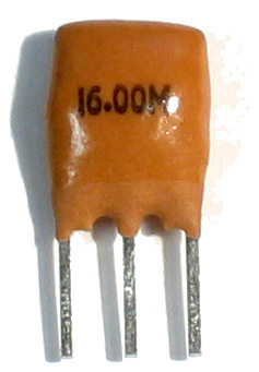
A ceramic resonator is an electronic component consisting of a piece of a piezoelectric ceramic material with two or more metal electrodes attached. When connected in an electronic oscillator circuit, resonant mechanical vibrations in the device generate an oscillating signal of a specific frequency. Like the similar quartz crystal, they are used in oscillators for purposes such as generating the clock signal used to control timing in computers and other digital logic devices, or generating the carrier signal in analog radio transmitters and receivers.
A frequency synthesizer is an electronic circuit that generates a range of frequencies from a single reference frequency. Frequency synthesizers are used in devices such as radio receivers, televisions, mobile telephones, radiotelephones, walkie-talkies, CB radios, cable television converter boxes, satellite receivers, and GPS systems. A frequency synthesizer may use the techniques of frequency multiplication, frequency division, direct digital synthesis, frequency mixing, and phase-locked loops to generate its frequencies. The stability and accuracy of the frequency synthesizer's output are related to the stability and accuracy of its reference frequency input. Consequently, synthesizers use stable and accurate reference frequencies, such as those provided by a crystal oscillator.
The Yaesu FT-ONE is an all-mode solid state general coverage HF amateur radio (HAM) transceiver. The use of FM required an optional FM board to be installed. The unit was designed for fixed, portable or mobile operation, although the size and weight (17 kg) made it more suitable for fixed use. The FT-ONE was built by the Japanese Yaesu-Musen Corporation from 1982 to 1986. At its release, the FT-ONE was launched as the successor to the FT-902 and as the new Yaesu top-of-the-line transceiver. The FT-ONE was not only Yaesu's first fully synthesized, computer-controlled amateur band transceiver but it was also the first transceiver with a general coverage receiver. The FT-ONE was sold in the U.S., Asian and European markets. It was released in 1982 with a list price of $2800.00 US.
The Yaesu FT-77 is a transceiver to be used in the 3,5 – 29,9 MHz shortwave radio amateur segment. This means the coverage of the 80-40-30-20-15-17-12 and 10 meter HF bands.

A shortwave radio receiver is a radio receiver that can receive one or more shortwave bands, between 1.6 and 30 MHz. A shortwave radio receiver often receives other broadcast bands, such as FM radio, Longwave and Mediumwave. Shortwave radio receivers are often used by dedicated hobbyists called shortwave listeners.


