Related Research Articles

An inductor, also called a coil, choke, or reactor, is a passive two-terminal electrical component that stores energy in a magnetic field when electric current flows through it. An inductor typically consists of an insulated wire wound into a coil.
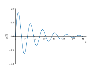
In physics and engineering, the quality factor or Q factor is a dimensionless parameter that describes how underdamped an oscillator or resonator is. It is defined as the ratio of the initial energy stored in the resonator to the energy lost in one radian of the cycle of oscillation. Q factor is alternatively defined as the ratio of a resonator's centre frequency to its bandwidth when subject to an oscillating driving force. These two definitions give numerically similar, but not identical, results. Higher Q indicates a lower rate of energy loss and the oscillations die out more slowly. A pendulum suspended from a high-quality bearing, oscillating in air, has a high Q, while a pendulum immersed in oil has a low one. Resonators with high quality factors have low damping, so that they ring or vibrate longer.

A crystal radio receiver, also called a crystal set, is a simple radio receiver, popular in the early days of radio. It uses only the power of the received radio signal to produce sound, needing no external power. It is named for its most important component, a crystal detector, originally made from a piece of crystalline mineral such as galena. This component is now called a diode.
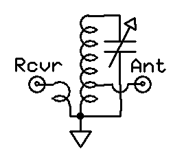
The Hartley oscillator is an electronic oscillator circuit in which the oscillation frequency is determined by a tuned circuit consisting of capacitors and inductors, that is, an LC oscillator. The circuit was invented in 1915 by American engineer Ralph Hartley. The distinguishing feature of the Hartley oscillator is that the tuned circuit consists of a single capacitor in parallel with two inductors in series, and the feedback signal needed for oscillation is taken from the center connection of the two inductors.
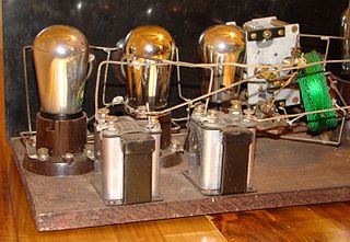
A tuned radio frequency receiver is a type of radio receiver that is composed of one or more tuned radio frequency (RF) amplifier stages followed by a detector (demodulator) circuit to extract the audio signal and usually an audio frequency amplifier. This type of receiver was popular in the 1920s. Early examples could be tedious to operate because when tuning in a station each stage had to be individually adjusted to the station's frequency, but later models had ganged tuning, the tuning mechanisms of all stages being linked together, and operated by just one control knob. By the mid 1930s, it was replaced by the superheterodyne receiver patented by Edwin Armstrong.

In radio communications, a radio receiver, also known as a receiver, a wireless, or simply a radio, is an electronic device that receives radio waves and converts the information carried by them to a usable form. It is used with an antenna. The antenna intercepts radio waves and converts them to tiny alternating currents which are applied to the receiver, and the receiver extracts the desired information. The receiver uses electronic filters to separate the desired radio frequency signal from all the other signals picked up by the antenna, an electronic amplifier to increase the power of the signal for further processing, and finally recovers the desired information through demodulation.
A resonator is a device or system that exhibits resonance or resonant behavior. That is, it naturally oscillates with greater amplitude at some frequencies, called resonant frequencies, than at other frequencies. The oscillations in a resonator can be either electromagnetic or mechanical. Resonators are used to either generate waves of specific frequencies or to select specific frequencies from a signal. Musical instruments use acoustic resonators that produce sound waves of specific tones. Another example is quartz crystals used in electronic devices such as radio transmitters and quartz watches to produce oscillations of very precise frequency.
An antenna tuner, a matchbox, transmatch, antenna tuning unit (ATU), antenna coupler, or feedline coupler is a device connected between a radio transmitter or receiver and its antenna to improve power transfer between them by matching the impedance of the radio to the antenna's feedline. Antenna tuners are particularly important for use with transmitters. Transmitters feed power into a resistive load, very often 50 ohms, for which the transmitter is optimally designed for power output, efficiency, and low distortion. If the load seen by the transmitter departs from this design value due to improper tuning of the antenna/feedline combination the power output will change, distortion may occur and the transmitter may overheat.

A spark-gap transmitter is an obsolete type of radio transmitter which generates radio waves by means of an electric spark. Spark-gap transmitters were the first type of radio transmitter, and were the main type used during the wireless telegraphy or "spark" era, the first three decades of radio, from 1887 to the end of World War I. German physicist Heinrich Hertz built the first experimental spark-gap transmitters in 1887, with which he proved the existence of radio waves and studied their properties.

Electronic filters are a type of signal processing filter in the form of electrical circuits. This article covers those filters consisting of lumped electronic components, as opposed to distributed-element filters. That is, using components and interconnections that, in analysis, can be considered to exist at a single point. These components can be in discrete packages or part of an integrated circuit.

A ‘T’-antenna, ‘T’-aerial, or flat-top antenna is a monopole radio antenna consisting of one or more horizontal wires suspended between two supporting radio masts or buildings and insulated from them at the ends. A vertical wire is connected to the center of the horizontal wires and hangs down close to the ground, connected to the transmitter or receiver. The shape of the antenna resembles the letter "T", hence the name. The transmitter power is applied, or the receiver is connected, between the bottom of the vertical wire and a ground connection.

A Q meter is a piece of equipment used in the testing of radio frequency circuits. It has been largely replaced in professional laboratories by other types of impedance measuring devices, though it is still in use among radio amateurs. It was developed at Boonton Radio Corporation in Boonton, New Jersey in 1934 by William D. Loughlin.

Electrical resonance occurs in an electric circuit at a particular resonant frequency when the impedances or admittances of circuit elements cancel each other. In some circuits, this happens when the impedance between the input and output of the circuit is almost zero and the transfer function is close to one.
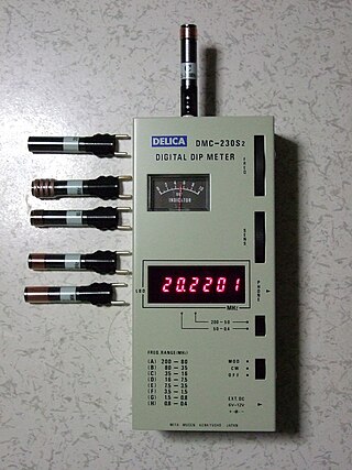
Grid dip oscillator (GDO), also called grid dip meter, gate dip meter, dip meter, or just dipper, is a type of electronic instrument that measures the resonant frequency of nearby unconnected radio frequency tuned circuits. It is a variable-frequency oscillator that circulates a small-amplitude signal through an exposed coil, whose electromagnetic field can interact with adjacent circuitry. The oscillator loses power when its coil is near a circuit that resonates at the same frequency. A meter on the GDO registers the amplitude drop, or "dip", hence the name.

Various types of electrical transformer are made for different purposes. Despite their design differences, the various types employ the same basic principle as discovered in 1831 by Michael Faraday, and share several key functional parts.
A preselector is a name for an electronic device that connects between a radio antenna and a radio receiver. The preselector is a band-pass filter that blocks troublesome out-of-tune frequencies from passing through from the antenna into the radio receiver that otherwise would be directly connected to the antenna.

Resonant inductive coupling or magnetic phase synchronous coupling is a phenomenon with inductive coupling in which the coupling becomes stronger when the "secondary" (load-bearing) side of the loosely coupled coil resonates. A resonant transformer of this type is often used in analog circuitry as a bandpass filter. Resonant inductive coupling is also used in wireless power systems for portable computers, phones, and vehicles.
Analogue filters are a basic building block of signal processing much used in electronics. Amongst their many applications are the separation of an audio signal before application to bass, mid-range, and tweeter loudspeakers; the combining and later separation of multiple telephone conversations onto a single channel; the selection of a chosen radio station in a radio receiver and rejection of others.

Basket winding is a winding method for electrical wire in a coil. The winding pattern is used for radio-frequency electronic components with many parallel wires, such as inductors and transformers. The winding pattern reduces the amount of wire running in adjacent, parallel turns. The wires in successive layers of a basket wound coil cross each other at large angles, as close to 90 degrees as possible, which reduces energy loss due to electrical cross-coupling between wires at radio frequencies.
An RLC circuit is an electrical circuit consisting of a resistor (R), an inductor (L), and a capacitor (C), connected in series or in parallel. The name of the circuit is derived from the letters that are used to denote the constituent components of this circuit, where the sequence of the components may vary from RLC.
References
- ↑ The American Radio Relay League: "The Radio Amateur's Handbook, 1968", page 112