The VHSIC Hardware Description Language (VHDL) is a hardware description language (HDL) that can model the behavior and structure of digital systems at multiple levels of abstraction, ranging from the system level down to that of logic gates, for design entry, documentation, and verification purposes. Since 1987, VHDL has been standardized by the Institute of Electrical and Electronics Engineers (IEEE) as IEEE Std 1076; the latest version of which is IEEE Std 1076-2019. To model analog and mixed-signal systems, an IEEE-standardized HDL based on VHDL called VHDL-AMS has been developed.
Verilog, standardized as IEEE 1364, is a hardware description language (HDL) used to model electronic systems. It is most commonly used in the design and verification of digital circuits at the register-transfer level of abstraction. It is also used in the verification of analog circuits and mixed-signal circuits, as well as in the design of genetic circuits. In 2009, the Verilog standard was merged into the SystemVerilog standard, creating IEEE Standard 1800-2009. Since then, Verilog is officially part of the SystemVerilog language. The current version is IEEE standard 1800-2017.
In computer engineering, a hardware description language (HDL) is a specialized computer language used to describe the structure and behavior of electronic circuits, and most commonly, digital logic circuits.
SPICE is a general-purpose, open-source analog electronic circuit simulator. It is a program used in integrated circuit and board-level design to check the integrity of circuit designs and to predict circuit behavior.
Electronic design automation (EDA), also referred to as electronic computer-aided design (ECAD), is a category of software tools for designing electronic systems such as integrated circuits and printed circuit boards. The tools work together in a design flow that chip designers use to design and analyze entire semiconductor chips. Since a modern semiconductor chip can have billions of components, EDA tools are essential for their design; this article in particular describes EDA specifically with respect to integrated circuits (ICs).

SystemVerilog, standardized as IEEE 1800, is a hardware description and hardware verification language used to model, design, simulate, test and implement electronic systems. SystemVerilog is based on Verilog and some extensions, and since 2008 Verilog is now part of the same IEEE standard. It is commonly used in the semiconductor and electronic design industry as an evolution of Verilog.

OrCAD Systems Corporation was a software company that made OrCAD, a proprietary software tool suite used primarily for electronic design automation (EDA). The software is used mainly by electronic design engineers and electronic technicians to create electronic schematics, perform mixed-signal simulation and electronic prints for manufacturing printed circuit boards (PCBs). OrCAD was taken over by Cadence Design Systems in 1999 and was integrated with Cadence Allegro since 2005.

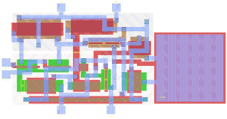
Integrated circuit design, or IC design, is a sub-field of electronics engineering, encompassing the particular logic and circuit design techniques required to design integrated circuits, or ICs. ICs consist of miniaturized electronic components built into an electrical network on a monolithic semiconductor substrate by photolithography.

In integrated circuit design, hardware emulation is the process of imitating the behavior of one or more pieces of hardware with another piece of hardware, typically a special purpose emulation system. The emulation model is usually based on a hardware description language source code, which is compiled into the format used by emulation system. The goal is normally debugging and functional verification of the system being designed. Often an emulator is fast enough to be plugged into a working target system in place of a yet-to-be-built chip, so the whole system can be debugged with live data. This is a specific case of in-circuit emulation.

Ngspice is an open-source mixed-level/mixed-signal electronic circuit simulator. It is a successor of the latest stable release of Berkeley SPICE, version 3f.5, which was released in 1993. A small group of maintainers and the user community contribute to the ngspice project by providing new features, enhancements and bug fixes.

Quite Universal Circuit Simulator (Qucs) is a free-software electronics circuit simulator software application released under GPL. It offers the ability to set up a circuit with a graphical user interface and simulate the large-signal, small-signal and noise behaviour of the circuit. Pure digital simulations are also supported using VHDL and/or Verilog.
Verilog-AMS is a derivative of the Verilog hardware description language that includes analog and mixed-signal extensions (AMS) in order to define the behavior of analog and mixed-signal systems. It extends the event-based simulator loops of Verilog/SystemVerilog/VHDL, by a continuous-time simulator, which solves the differential equations in analog-domain. Both domains are coupled: analog events can trigger digital actions and vice versa.

Electronic circuit simulation uses mathematical models to replicate the behavior of an actual electronic device or circuit. Simulation software allows for modeling of circuit operation and is an invaluable analysis tool. Due to its highly accurate modeling capability, many colleges and universities use this type of software for the teaching of electronics technician and electronics engineering programs. Electronics simulation software engages its users by integrating them into the learning experience. These kinds of interactions actively engage learners to analyze, synthesize, organize, and evaluate content and result in learners constructing their own knowledge.
Value Change Dump (VCD) is an ASCII-based format for dumpfiles generated by EDA logic simulation tools. The standard, four-value VCD format was defined along with the Verilog hardware description language by the IEEE Standard 1364-1995 in 1996. An Extended VCD format defined six years later in the IEEE Standard 1364-2001 supports the logging of signal strength and directionality. The simple and yet compact structure of the VCD format has allowed its use to become ubiquitous and to spread into non-Verilog tools such as the VHDL simulator GHDL and various kernel tracers. A limitation of the format is that it is unable to record the values in memories.
Aldec, Inc. is a privately owned electronic design automation company based in Henderson, Nevada that provides software and hardware used in creation and verification of digital designs targeting FPGA and ASIC technologies.
A Bus Functional Model or BFM is a non-synthesizable software model of an integrated circuit component having one or more external buses. The emphasis of the model is on simulating system bus transactions prior to building and testing the actual hardware. BFMs are usually defined as tasks in Hardware description languages (HDLs), which apply stimuli to the design under verification via complex waveforms and protocols. A BFM is typically implemented using hardware description languages such as Verilog, VHDL, SystemC, or SystemVerilog.
Spectre is a SPICE-class circuit simulator owned and distributed by the software company Cadence Design Systems. It provides the basic SPICE analyses and component models. It also supports the Verilog-A modeling language. Spectre comes in enhanced versions that also support RF simulation (SpectreRF) and mixed-signal simulation.
This page is a comparison of electronic design automation (EDA) software which is used today to design the near totality of electronic devices. Modern electronic devices are too complex to be designed without the help of a computer. Electronic devices may consist of integrated circuits (ICs), printed circuit boards (PCBs), field programmable gate arrays (FPGAs) or a combination of them. Integrated circuits may consist of a combination of digital and analog circuits. These circuits can contain a combination of transistors, resistors, capacitors or specialized components such as analog neural networks, antennas or fuses.

Xilinx ISE is a discontinued software tool from Xilinx for synthesis and analysis of HDL designs, which primarily targets development of embedded firmware for Xilinx FPGA and CPLD integrated circuit (IC) product families. It was succeeded by Xilinx Vivado. Use of the last released edition from October 2013 continues for in-system programming of legacy hardware designs containing older FPGAs and CPLDs otherwise orphaned by the replacement design tool, Vivado Design Suite.


