
An operational amplifier is a DC-coupled high-gain electronic voltage amplifier with a differential input and, usually, a single-ended output. In this configuration, an op amp produces an output potential that is typically 100,000 times larger than the potential difference between its input terminals. Operational amplifiers had their origins in analog computers, where they were used to perform mathematical operations in linear, non-linear, and frequency-dependent circuits.

In electronics, an analog-to-digital converter is a system that converts an analog signal, such as a sound picked up by a microphone or light entering a digital camera, into a digital signal. An ADC may also provide an isolated measurement such as an electronic device that converts an analog input voltage or current to a digital number representing the magnitude of the voltage or current. Typically the digital output is a two's complement binary number that is proportional to the input, but there are other possibilities.

In electronics, a comparator is a device that compares two voltages or currents and outputs a digital signal indicating which is larger. It has two analog input terminals and and one binary digital output . The output is ideally

A phase-locked loop or phase lock loop (PLL) is a control system that generates an output signal whose phase is related to the phase of an input signal. There are several different types; the simplest is an electronic circuit consisting of a variable frequency oscillator and a phase detector in a feedback loop. The oscillator's frequency and phase are controlled proportionally by an applied voltage, hence the term voltage-controlled oscillator (VCO). The oscillator generates a periodic signal of a specific frequency, and the phase detector compares the phase of that signal with the phase of the input periodic signal, to adjust the oscillator to keep the phases matched.
Transistor–transistor logic (TTL) is a logic family built from bipolar junction transistors. Its name signifies that transistors perform both the logic function and the amplifying function, as opposed to resistor–transistor logic (RTL) or diode–transistor logic (DTL).

A rectifier is an electrical device that converts alternating current (AC), which periodically reverses direction, to direct current (DC), which flows in only one direction. The reverse operation is performed by the inverter.

In electronics a relaxation oscillator is a nonlinear electronic oscillator circuit that produces a nonsinusoidal repetitive output signal, such as a triangle wave or square wave. The circuit consists of a feedback loop containing a switching device such as a transistor, comparator, relay, op amp, or a negative resistance device like a tunnel diode, that repetitively charges a capacitor or inductor through a resistance until it reaches a threshold level, then discharges it again. The period of the oscillator depends on the time constant of the capacitor or inductor circuit. The active device switches abruptly between charging and discharging modes, and thus produces a discontinuously changing repetitive waveform. This contrasts with the other type of electronic oscillator, the harmonic or linear oscillator, which uses an amplifier with feedback to excite resonant oscillations in a resonator, producing a sine wave. Relaxation oscillators are used to produce low frequency signals for applications such as blinking lights and electronic beepers and in voltage controlled oscillators (VCOs), inverters and switching power supplies, dual-slope analog to digital converters, and function generators.
A phase detector or phase comparator is a frequency mixer, analog multiplier or logic circuit that generates a signal which represents the difference in phase between two signal inputs.

In electronics, a Schmitt trigger is a comparator circuit with hysteresis implemented by applying positive feedback to the noninverting input of a comparator or differential amplifier. It is an active circuit which converts an analog input signal to a digital output signal. The circuit is named a trigger because the output retains its value until the input changes sufficiently to trigger a change. In the non-inverting configuration, when the input is higher than a chosen threshold, the output is high. When the input is below a different (lower) chosen threshold the output is low, and when the input is between the two levels the output retains its value. This dual threshold action is called hysteresis and implies that the Schmitt trigger possesses memory and can act as a bistable multivibrator. There is a close relation between the two kinds of circuits: a Schmitt trigger can be converted into a latch and a latch can be converted into a Schmitt trigger.

The 555 timer IC is an integrated circuit (chip) used in a variety of timer, delay, pulse generation, and oscillator applications. Derivatives provide two (556) or four (558) timing circuits in one package. The design was first marketed in 1972 by Signetics. Since then, numerous companies have made the original bipolar timers, as well as similar low-power CMOS timers. In 2017, it was said that over a billion 555 timers are produced annually by some estimates, and that the design was "probably the most popular integrated circuit ever made".

A voltage regulator is a system designed to automatically maintain a constant voltage. A voltage regulator may use a simple feed-forward design or may include negative feedback. It may use an electromechanical mechanism, or electronic components. Depending on the design, it may be used to regulate one or more AC or DC voltages.
A voltage doubler is an electronic circuit which charges capacitors from the input voltage and switches these charges in such a way that, in the ideal case, exactly twice the voltage is produced at the output as at its input.
Delta-sigma modulation is a method for encoding analog signals into digital signals as found in an analog-to-digital converter (ADC). It is also used to convert high bit-count, low-frequency digital signals into lower bit-count, higher-frequency digital signals as part of the process to convert digital signals into analog as part of a digital-to-analog converter (DAC).
The cascode is a two-stage amplifier that consists of a common-emitter stage feeding into a common-base stage.

XOR gate is a digital logic gate that gives a true output when the number of true inputs is odd. An XOR gate implements an exclusive or from mathematical logic; that is, a true output results if one, and only one, of the inputs to the gate is true. If both inputs are false (0/LOW) or both are true, a false output results. XOR represents the inequality function, i.e., the output is true if the inputs are not alike otherwise the output is false. A way to remember XOR is "must have one or the other but not both".

In radio, a detector is a device or circuit that extracts information from a modulated radio frequency current or voltage. The term dates from the first three decades of radio (1888-1918). Unlike modern radio stations which transmit sound on an uninterrupted carrier wave, early radio stations transmitted information by radiotelegraphy. The transmitter was switched on and off to produce long or short periods of radio waves, spelling out text messages in Morse code. Therefore, early radio receivers had only to distinguish between the presence or absence of a radio signal. The device that performed this function in the receiver circuit was called a detector. A variety of different detector devices, such as the coherer, electrolytic detector, magnetic detector and the crystal detector, were used during the wireless telegraphy era until superseded by vacuum tube technology.
A flash ADC is a type of analog-to-digital converter that uses a linear voltage ladder with a comparator at each "rung" of the ladder to compare the input voltage to successive reference voltages. Often these reference ladders are constructed of many resistors; however, modern implementations show that capacitive voltage division is also possible. The output of these comparators is generally fed into a digital encoder, which converts the inputs into a binary value.
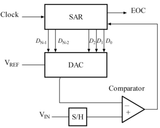
A successive-approximation ADC is a type of analog-to-digital converter that converts a continuous analog waveform into a discrete digital representation using a binary search through all possible quantization levels before finally converging upon a digital output for each conversion.

A clamper is an electronic circuit that fixes either the positive or the negative peak excursions of a signal to a defined value by shifting its DC value. The clamper does not restrict the peak-to-peak excursion of the signal, it moves the whole signal up or down so as to place the peaks at the reference level. A diode clamp consists of a diode, which conducts electric current in only one direction and prevents the signal exceeding the reference value; and a capacitor, which provides a DC offset from the stored charge. The capacitor forms a time constant with a resistor load, which determines the range of frequencies over which the clamper will be effective.
A comparator is an electronic component that compares two input voltages. Comparators are closely related to operational amplifiers, but a comparator is designed to operate with positive feedback and with its output saturated at one power rail or the other. An op-amp can be pressed into service as a poorly performing comparator if necessary, but its slew Rate will be impaired.
