Calipers or callipers are an instrument used to measure the linear dimensions of an object or hole; namely, the length, width, thickness, diameter or depth of an object or hole. The word caliper comes from a corrupt form of caliber.[1][2][3]
Many types of calipers permit reading out a measurement on a ruled scale, a dial, or an electronic digital display. A common association is to calipers using a sliding vernier scale.
Some calipers can be as simple as a compass with inward or outward-facing points, but with no scale (measurement indication). The tips of the caliper are adjusted to fit across the points to be measured, and then kept at that span while moved to separate measuring device, such as a ruler, or simply transferred directly to a workpiece.
Caliper is the American spelling, while calliper (double "L") is the British spelling.
A single tool might be referred to as a caliper or as calipers–a plural only (plurale tantum) form, like scissors or glasses.
Colloquially, the phrase "pair of verniers" or just "vernier" might refer to a vernier caliper. In loose colloquial usage, these phrases may also refer to other kinds of calipers, although they involve no vernier scale. In machine-shop usage, the term "caliper" is often used in contradistinction to micrometer, even though outside micrometers are a form of caliper. In this usage, caliper implies only the form factor of the instrument.
The earliest caliper has been found in the GreekGiglio wreck near the Italian coast. The ship's find dates to the 6th century BC. The wooden piece already featured a fixed and a movable jaw.[4][5] Although rare finds, calipers remained in use by the Greeks and Romans.[5][6]
A bronze caliper, dating from 9 AD, was used for minute measurements during the Chinese Xin dynasty. The caliper had an inscription stating that it was "made on the gui-you day,[a] the first day[b] of the first month of the first year of Shijianguo.[c]" The calipers included a "slot and pin" and "graduated in inches and tenths of an inch."[7][8]
Inside calipers are used to measure the internal size of an object.
The upper caliper in the image (on the right) requires manual adjustment prior to fitting. Fine setting of this caliper type is performed by tapping the caliper legs lightly on a handy surface until they will almost pass over the object. A light push against the resistance of the central pivot screw then spreads the legs to the correct dimension and provides the required, consistent feel that ensures a repeatable measurement.
The lower caliper in the image has an adjusting screw that permits it to be carefully adjusted without removal of the tool from the workpiece.
Outside caliper
Three outside calipers
Outside calipers are used to measure the external size of an object.
The same observations and technique apply to this type of caliper, as for the inside caliper. With some understanding of their limitations and usage, these instruments can provide a high degree of accuracy and repeatability. They are especially useful when measuring over very large distances; consider if the calipers are used to measure a large-diameter pipe. A vernier caliper does not have the depth capacity to straddle this large diameter and at the same time reach the outermost points of the pipe's diameter. They are made from high-carbon steel.
"Dividers" redirects here. For the sculpture by Vivien Burnside, see Dividers (sculpture).
A pair of dividers
In the metalworking field, a divider caliper, popularly called a compass, is used to mark out locations. The points are sharpened so that they act as scribers; one leg can then be placed in the dimple created by a center or prick punch and the other leg pivoted so that it scribes a line on the workpiece's surface, thus forming an arc or circle.
Their namesake use is in dividing a workpiece of arbitrary width into equal-width sections: by "walking" the tool from one end to the other by pivoting it from one point to the next until reaching the other end, then adjusting the gap between the points until the "walk" ends directly on the end point, equal divisions can be easily marked out without any measuring.
A divider caliper is also used to measure a distance between two points on a map. The two caliper ends are brought to the two points whose distance is being measured. The caliper's opening is then either measured on a separate ruler and then converted to the actual distance, or measured directly on a scale drawn on the map. On a nautical chart the distance is often measured on the latitude scale appearing on the sides of the map: one minute of arc along any great circle, e.g. any longitude meridian, is approximately one nautical mile or 1852 meters.
Dividers are also used in the medical profession. An ECG (also EKG) caliper transfers distance on an electrocardiogram; in conjunction with the appropriate scale, the heart rate can be determined. A pocket caliper version was invented by cardiologist Robert A. Mackin.[9][failed verification]
Oddleg caliper
Oddleg calipers
Oddleg calipers, hermaphrodite calipers, or oddleg jennys, as pictured on the left, are generally used to scribe a line at a set distance from the edge of a workpiece. The bent leg is used to run along the workpiece edge while the scriber makes its mark at a predetermined distance, this ensures a line parallel to the edge.
In the diagram at left, the uppermost caliper has a slight shoulder in the bent leg allowing it to sit on the edge more securely. The lower caliper lacks this feature but has a renewable scriber that can be adjusted for wear, as well as being replaced when excessively worn.
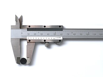
Outside large jaws: used to measure external diameter of an object (like a hollow cylinder) or width of an object (like a rod), diameter of an object (like a sphere).
Inside small jaws: used to measure the internal diameter of an object (like a hollow cylinder or pipe).
Depth probe, or depth rod: used to measure depths of an object (like a small beaker) or a hole.
Main scale (metric): marked every millimeter and helps to measure length correct up to 1mm.
Main scale (imperial): marked in inches and fractions.
Vernier scale (metric) gives interpolated measurements to 0.1mm or better.
Vernier scale (imperial) gives interpolated measurements in fractions of an inch.
Retainer: used to block movable part to allow the easy transferring of a measurement.
The calipers in the diagram show a primary reading on the metric scale of about 2.475cm (2.4cm read from the main scale plus about 0.075cm from the vernier scale).
Calipers often have a "zero point error": meaning that the calipers do not read 0.000cm when the jaws are closed. The zero point error must always be subtracted from the primary reading. Let us assume these calipers have a zero-point error of 0.013cm. This would give us a length reading of 2.462cm.
For any measurement, reporting the error on the measurement is also important. Ignoring the possibility of interpolation by eye, both the primary reading and the zero point reading are bounded by plus/minus half the length corresponding to the width of the smallest interval on the vernier scale (0.0025cm). These are "absolute" errors and absolute errors add, so the length reading is then bounded by plus/minus the length corresponding to the full width of the smallest interval on the vernier scale (0.005cm). Assuming no systematics affect the measurement (the instrument works perfectly), a complete measurement would then read 2.462cm ± 0.005cm.
The vernier, dial, and digital calipers directly read the distance measured with high accuracy and precision. They are functionally identical, with different ways of reading the result. These calipers comprise a calibrated scale with a fixed jaw, and another jaw, with a pointer, that slides along the scale. The distance between the jaws is then read in different ways for the three types.
The simplest method is to read the position of the pointer directly on the scale. When the pointer is between two markings, the user can mentally interpolate to improve the precision of the reading. This would be a simply calibrated caliper, but the addition of a vernier scale allows more accurate interpolation and is the universal practice; this is the vernier caliper.
Vernier, dial, and digital calipers can measure internal dimensions (using the uppermost jaws in the picture at right), external dimensions using the pictured lower jaws, and in many cases depth by the use of a probe that is attached to the movable head and slides along the centre of the body. This probe is slender and can get into deep grooves that may prove difficult for other measuring tools.
The vernier scales may include metric measurements on the lower part of the scale and inch measurements on the upper, or vice versa, in countries that use inches. Vernier calipers commonly used in industry provide a precision to 0.01mm (10 micrometres), or one thousandth of an inch. They are available in sizes that can measure up to 1828mm (72in).[10]
Measuring with vernier calipers
Measuring external distance
Measuring internal distance
Measuring the depth of a step or hole with the depth probe
Measuring the width of a step with the top of the calipers
Marking with Vernier calipers
Marking a set or measured distance from an edge by scraping a line with the sharp sides of the beak
Marking a set or measured distance from an edge by marking with a pencil. The top of the moving part is held against the side of the step. Not all calipers have this option.
Dial caliper
Dial caliper
Instead of using a vernier mechanism, which requires some practice to use, the dial caliper reads the final fraction of a millimeter or inch on a simple dial.
In this instrument, a small, precise rack and pinion drives a pointer on a circular dial, allowing direct reading without the need to read a vernier scale. Typically, the pointer rotates once every inch, tenth of an inch, or 1 millimeter. This measurement must be added to the coarse whole inches or centimeters read from the slide. The dial is usually arranged to be rotatable beneath the pointer, allowing for "differential" measurements (the measuring of the difference in size between two objects, or the setting of the dial using a master object and subsequently being able to read directly the plus-or-minus variance in the size of subsequent objects relative to the master object).
The slide of a dial caliper can usually be locked at a setting using a small lever or screw; this allows simple go/no-go checks of part sizes.
Digital caliper
Digital caliper
Rather than a rack and pinion, digital calipers use a linear encoder. A liquid-crystal display shows the measurement, which often can switch units between millimeters and fractional or decimal inches. All provide for zeroing the display at any point along the slide, allowing the same sort of differential measurements as with the dial caliper. Digital calipers may contain a "reading hold" feature, allowing the reading of dimensions after use in awkward locations where the display cannot be seen. Like analog calipers, the slide of many digital calipers can be locked using a lever or screw.
Resolution and accuracy
Ordinary 150mm (6in) digital calipers made of stainless steel have a rated accuracy of ± 0.02mm (0.001in) and a resolution of 0.01mm (0.0005in).[11] The same technology is used for longer calipers, but accuracy declines to ± 0.03mm (0.001in) for 100–200mm (4–8in) and ± 0.04mm (0.0015in) for 200–300mm (8–12in) measurements.[12]
Measurement method
USpatent filing[13] corresponding to a 1983 German patent DE3340782C2[14] for a "capacitive displacement measuring device with t-shaped scale coatings", whose abstract describes it as follows: a capacitance length and/or angle measuring device has a transducer comprising a stationary part forming a scale and a sensing unit, both provided with capacitive coatings. Changing their overlapping area results in a variable capacitive reactance, which changes the phase position of the electrical signals. A linear function between the mechanical quantity to be measured and the phase portion of the signals can be obtained with an appropriate configuration of the capacitor surfaces.
Many digital calipers contain a capacitive linear encoder. Inexpensive models have 56 narrow emitter plates and one long receiver plate etched on the sliding display's printed circuit board, which intersect with a repeating pattern of T-shaped plates in the longer "stator" board. The top of the "T" plates intersect with the receiver plate, while the vertical bars of each "T" intersect with the emitter plates. The pitch of each "T" in the stator is slightly less than 8 times the pitch of each emitter plate, so their intersecting capacitive area is not perfectly aligned but rather forms an interference pattern.[15] As the slider moves, these variable capacitances change in a repeating linear fashion. The slider's circuitry counts these repetitions as it slides and achieves finer resolution using linear interpolation of the capacitances.[16] One model sends 8 periodic pulse-width modulation voltage signals (which appear identical but out of phase by 1⁄8 of the period),[17] each connected to 7 emitter plates, and the resulting analog signal is read through a single receiver plate.[18] The 1983 German patent DE3340782C2 (see figure) is said to describe the workings.[19]
Other digital calipers contain an inductive linear encoder, which allows robust performance in the presence of contamination such as coolants.[20] Magnetic linear encoders are used in yet other digital calipers.[citation needed]
A caliper using a calibrated screw for measurement (rather than a slide) is called an external micrometer caliper gauge, a micrometer caliper, or, more often, simply a micrometer. Sometimes the term caliper, referring to any other type in this article, is held in contradistinction to micrometer.
Comparison
Each of the above types of calipers has its relative merits and faults.
Vernier calipers are rugged and have long-lasting accuracy, are coolant proof, are not affected by magnetic fields, and are largely shockproof. They may have both centimeter and inch scales. However, vernier calipers require good eyesight or a magnifying glass to read and can be difficult to read from a distance or from awkward angles. It is relatively easy to misread the last digit. In production environments, reading vernier calipers all day long is error-prone and is annoying to the workers.
Dial calipers are comparatively easy to read, especially when seeking the exact center by rocking and observing the needle movement. They can be set to 0 at any point for comparisons. They are usually fairly susceptible to shock damage. They are also very prone to getting dirt in the gears, which can cause accuracy problems.
Digital calipers switch easily between centimeter and inch systems. They can be set to zero easily at any point with a full count in either direction and can take measurements even if the display is completely hidden, either by using a "hold" key, or by zeroing the display and closing the jaws, showing the correct measurement, but negative. They can be mechanically and electronically fragile. Most also require batteries and do not resist coolant well. They are also only moderately shockproof and can be vulnerable to dirt.
Calipers may read to a resolution of 0.01mm or 0.0005in, but accuracy may not be better than about ±0.02mm or 0.001in for 150mm (6in) calipers, and worse for longer ones.[28]
Use
Using the vernier caliperA biologist uses calipers to measure the length of a bird's leg
A caliper must be properly applied against the part in order to take the desired measurement. For example, when measuring the thickness of a plate, a vernier caliper must be held at right angles to the piece. Some practice may be needed to measure round or irregular objects correctly.
Accuracy of measurement when using a caliper is highly dependent on the skill of the operator. Regardless of type, a caliper's jaws must be forced into contact with the part being measured. As both part and caliper are always to some extent elastic, the amount of force used affects the indication. A consistent, firm touch is correct. Too much force results in an under indication as part and tool distort; too little force gives insufficient contact and an over indication. This is a greater problem with a caliper incorporating a wheel, which lends mechanical advantage. This is especially the case with digital calipers, calipers out of adjustment, or calipers with a poor quality beam.
Simple calipers are uncalibrated; the measurement taken must be compared against a scale. Whether the scale is part of the caliper or not, all analog calipers—verniers and dials—require good eyesight in order to achieve the highest precision. Digital calipers have an advantage in this area.
Calibrated calipers may be mishandled, leading to loss of zero. When a caliper's jaws are fully closed, it should, of course, indicate zero. If it does not, it must be recalibrated or repaired. A vernier caliper does not easily lose its calibration, but a sharp impact or accidental damage to the measuring surface in the caliper jaw can be significant enough to displace zero.[29] Digital calipers have zero set buttons, for quick recalibration.
Vernier, dial and digital calipers can be used with accessories that extend their usefulness. Examples are a base that extends their usefulness as a depth gauge and a jaw attachment that all allows measuring the center distance between holes. Since the 1970s, a clever modification of the moveable jaw on the back side of any caliper allows for step or depth measurements in addition to external caliper measurements, similarly to a universal micrometer (e.g., Starrett Mul-T-Anvil or Mitutoyo Uni-Mike).
Zero error
If when the jaws are closed the reading is 0.10mm, the zero error is +0.10mm. The method to use a vernier scale or caliper with zero error is to use the formula "(actual reading) = (main scale) + (vernier scale) − (zero error)", thus the actual reading is 19.00 + 0.54 − (0.10) = 19.44mm. The resolution of the measurement, based on the width of the smallest sub-interval, is ±0.02mm.
The method to use a vernier scale or caliper with zero error is to use the formula "actual reading = main scale + vernier scale − (zero error)". Zero error may arise due to knocks that affect the calibration at 0.00mm when the jaws are perfectly closed or just touching each other. Positive zero error refers to the fact that when the jaws of the vernier caliper are just closed, the reading is a positive reading away from the actual reading of 0.00mm. If the reading is 0.10mm, the zero error is referred to as +0.10mm. Negative zero error refers to the fact that when the jaws of the vernier caliper are just closed, the reading is a negative reading away from the actual reading of 0.00mm. If the reading is −0.08mm, the zero error is referred to as −0.08mm.
Abbe error
Comparison of Abbe error for Vernier calipers and a micrometer
Calipers with measurement axes displaced from the object being measured suffer from Abbe error if the jaws are not perpendicular due to manufacturing tolerances. Unlike zero error, the amount of Abbe error depends on the offset.[30]
↑Shijianguo is the first era name of Wang Mang, the first and only emperor of the Xin dynasty, lit. "the beginning of a nation's establishment."
References
↑"caliper". Merriam-Webster. Merriam-Webster Inc. Retrieved 2023-04-22.
↑"caliper". Collins English Dictionary. HarperCollins Publishers. Retrieved 2023-04-22.
↑"calipers". Cambridge English Dictionary. Cambridge University Press. Retrieved 2023-04-22.
↑Mensun Bound: The Giglio wreck: a wreck of the Archaic period (c. 600 BC) off the Tuscany island of Giglio, Hellenic Institute of Marine Archaeology, Athens 1991, pp. 27 and 31 (Fig. 65)
12Roger B. Ulrich: Roman woodworking, Yale University Press, New Haven, Conn., 2007, ISBN0-300-10341-7, p.52f.
This page is based on this Wikipedia article Text is available under the CC BY-SA 4.0 license; additional terms may apply. Images, videos and audio are available under their respective licenses.


