Statics is the branch of classical mechanics that is concerned with the analysis of force and torque acting on a physical system that does not experience an acceleration, but rather is in equilibrium with its environment.
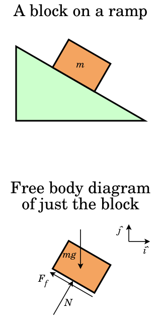
In physics and engineering, a free body diagram is a graphical illustration used to visualize the applied forces, moments, and resulting reactions on a free body in a given condition. It depicts a body or connected bodies with all the applied forces and moments, and reactions, which act on the body(ies). The body may consist of multiple internal members, or be a compact body. A series of free bodies and other diagrams may be necessary to solve complex problems. Sometimes in order to calculate the resultant force graphically the applied forces are arranged as the edges of a polygon of forces or force polygon.
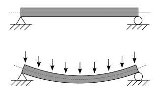
A beam is a structural element that primarily resists loads applied laterally across the beam's axis. Its mode of deflection is primarily by bending, as loads produce reaction forces at the beam's support points and internal bending moments, shear, stresses, strains, and deflections. Beams are characterized by their manner of support, profile, equilibrium conditions, length, and material.
In statics and structural mechanics, a structure is statically indeterminate when the equilibrium equations – force and moment equilibrium conditions – are insufficient for determining the internal forces and reactions on that structure.

In applied mechanics, bending characterizes the behavior of a slender structural element subjected to an external load applied perpendicularly to a longitudinal axis of the element.

Euler–Bernoulli beam theory is a simplification of the linear theory of elasticity which provides a means of calculating the load-carrying and deflection characteristics of beams. It covers the case corresponding to small deflections of a beam that is subjected to lateral loads only. By ignoring the effects of shear deformation and rotatory inertia, it is thus a special case of Timoshenko–Ehrenfest beam theory. It was first enunciated circa 1750, but was not applied on a large scale until the development of the Eiffel Tower and the Ferris wheel in the late 19th century. Following these successful demonstrations, it quickly became a cornerstone of engineering and an enabler of the Second Industrial Revolution.
Castigliano's method, named after Carlo Alberto Castigliano, is a method for determining the displacements of a linear-elastic system based on the partial derivatives of the energy. He is known for his two theorems. The basic concept may be easy to understand by recalling that a change in energy is equal to the causing force times the resulting displacement. Therefore, the causing force is equal to the change in energy divided by the resulting displacement. Alternatively, the resulting displacement is equal to the change in energy divided by the causing force. Partial derivatives are needed to relate causing forces and resulting displacements to the change in energy.
This is an alphabetical list of articles pertaining specifically to structural engineering. For a broad overview of engineering, please see List of engineering topics. For biographies please see List of engineers.
Structural dynamics is a type of structural analysis which covers the behavior of a structure subjected to dynamic loading. Dynamic loads include people, wind, waves, traffic, earthquakes, and blasts. Any structure can be subjected to dynamic loading. Dynamic analysis can be used to find dynamic displacements, time history, and modal analysis.
The moment distribution method is a structural analysis method for statically indeterminate beams and frames developed by Hardy Cross. It was published in 1930 in an ASCE journal. The method only accounts for flexural effects and ignores axial and shear effects. From the 1930s until computers began to be widely used in the design and analysis of structures, the moment distribution method was the most widely practiced method.
The slope deflection method is a structural analysis method for beams and frames introduced in 1914 by George A. Maney. The slope deflection method was widely used for more than a decade until the moment distribution method was developed. In the book, "The Theory and Practice of Modern Framed Structures", written by J.B Johnson, C.W. Bryan and F.E. Turneaure, it is stated that this method was first developed "by Professor Otto Mohr in Germany, and later developed independently by Professor G.A. Maney". According to this book, professor Otto Mohr introduced this method for the first time in his book, "Evaluation of Trusses with Rigid Node Connections" or "Die Berechnung der Fachwerke mit Starren Knotenverbindungen".

The Timoshenko–Ehrenfest beam theory was developed by Stephen Timoshenko and Paul Ehrenfest early in the 20th century. The model takes into account shear deformation and rotational bending effects, making it suitable for describing the behaviour of thick beams, sandwich composite beams, or beams subject to high-frequency excitation when the wavelength approaches the thickness of the beam. The resulting equation is of 4th order but, unlike Euler–Bernoulli beam theory, there is also a second-order partial derivative present. Physically, taking into account the added mechanisms of deformation effectively lowers the stiffness of the beam, while the result is a larger deflection under a static load and lower predicted eigenfrequencies for a given set of boundary conditions. The latter effect is more noticeable for higher frequencies as the wavelength becomes shorter, and thus the distance between opposing shear forces decreases.

Direct integration is a structural analysis method for measuring internal shear, internal moment, rotation, and deflection of a beam.
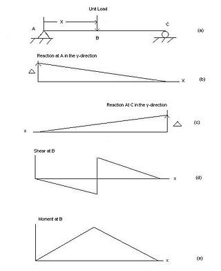
In engineering, an influence line graphs the variation of a function at a specific point on a beam or truss caused by a unit load placed at any point along the structure. Common functions studied with influence lines include reactions, shear, moment, and deflection (Deformation). Influence lines are important in designing beams and trusses used in bridges, crane rails, conveyor belts, floor girders, and other structures where loads will move along their span. The influence lines show where a load will create the maximum effect for any of the functions studied.
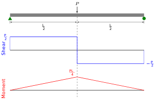
Shear force and bending moment diagrams are analytical tools used in conjunction with structural analysis to help perform structural design by determining the value of shear forces and bending moments at a given point of a structural element such as a beam. These diagrams can be used to easily determine the type, size, and material of a member in a structure so that a given set of loads can be supported without structural failure. Another application of shear and moment diagrams is that the deflection of a beam can be easily determined using either the moment area method or the conjugate beam method.

In structural engineering, deflection is the degree to which a part of a long structural element is deformed laterally under a load. It may be quantified in terms of an angle or a distance . A longitudinal deformation is called elongation.

Structural engineering depends upon a detailed knowledge of loads, physics and materials to understand and predict how structures support and resist self-weight and imposed loads. To apply the knowledge successfully structural engineers will need a detailed knowledge of mathematics and of relevant empirical and theoretical design codes. They will also need to know about the corrosion resistance of the materials and structures, especially when those structures are exposed to the external environment.
In civil engineering and structural analysis Clapeyron'stheorem of three moments is a relationship among the bending moments at three consecutive supports of a horizontal beam.
The Müller-Breslau principle is a method to determine influence lines. The principle states that the influence lines of an action assumes the scaled form of the deflection displacement. OR, This principle states that "ordinate of ILD for a reactive force is given by ordinate of elastic curve if a unit deflection is applied in the direction of reactive force."
The moment-area theorem is an engineering tool to derive the slope, rotation and deflection of beams and frames. This theorem was developed by Mohr and later stated namely by Charles Ezra Greene in 1873. This method is advantageous when we solve problems involving beams, especially for those subjected to a series of concentrated loadings or having segments with different moments of inertia.