
In mathematics, the slope or gradient of a line is a number that describes both the direction and the steepness of the line. Slope is often denoted by the letter m; there is no clear answer to the question why the letter m is used for slope, but its earliest use in English appears in O'Brien (1844) who wrote the equation of a straight line as "y = mx + b" and it can also be found in Todhunter (1888) who wrote it as "y = mx + c".

Stiffness is the extent to which an object resists deformation in response to an applied force.
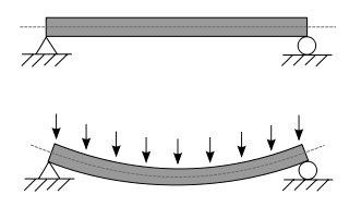
A beam is a structural element that primarily resists loads applied laterally to the beam's axis. Its mode of deflection is primarily by bending. The loads applied to the beam result in reaction forces at the beam's support points. The total effect of all the forces acting on the beam is to produce shear forces and bending moments within the beams, that in turn induce internal stresses, strains and deflections of the beam. Beams are characterized by their manner of support, profile, equilibrium conditions, length, and their material.

In structural engineering, buckling is the sudden change in shape (deformation) of a structural component under load, such as the bowing of a column under compression or the wrinkling of a plate under shear. If a structure is subjected to a gradually increasing load, when the load reaches a critical level, a member may suddenly change shape and the structure and component is said to have buckled. Euler's critical load and Johnson's parabolic formula are used to determine the buckling stress of a column.

In applied mechanics, bending characterizes the behavior of a slender structural element subjected to an external load applied perpendicularly to a longitudinal axis of the element.
Flexural rigidity is defined as the force couple required to bend a fixed non-rigid structure by one unit of curvature, or as the resistance offered by a structure while undergoing bending.

Euler–Bernoulli beam theory is a simplification of the linear theory of elasticity which provides a means of calculating the load-carrying and deflection characteristics of beams. It covers the case corresponding to small deflections of a beam that is subjected to lateral loads only. By ignoring the effects of shear deformation and rotatory inertia, it is thus a special case of Timoshenko–Ehrenfest beam theory. It was first enunciated circa 1750, but was not applied on a large scale until the development of the Eiffel Tower and the Ferris wheel in the late 19th century. Following these successful demonstrations, it quickly became a cornerstone of engineering and an enabler of the Second Industrial Revolution.
Castigliano's method, named after Carlo Alberto Castigliano, is a method for determining the displacements of a linear-elastic system based on the partial derivatives of the energy. He is known for his two theorems. The basic concept may be easy to understand by recalling that a change in energy is equal to the causing force times the resulting displacement. Therefore, the causing force is equal to the change in energy divided by the resulting displacement. Alternatively, the resulting displacement is equal to the change in energy divided by the causing force. Partial derivatives are needed to relate causing forces and resulting displacements to the change in energy.

The three-point bending flexural test provides values for the modulus of elasticity in bending , flexural stress , flexural strain and the flexural stress–strain response of the material. This test is performed on a universal testing machine with a three-point or four-point bend fixture. The main advantage of a three-point flexural test is the ease of the specimen preparation and testing. However, this method has also some disadvantages: the results of the testing method are sensitive to specimen and loading geometry and strain rate.

In differential geometry, the notion of torsion is a manner of characterizing a twist or screw of a moving frame around a curve. The torsion of a curve, as it appears in the Frenet–Serret formulas, for instance, quantifies the twist of a curve about its tangent vector as the curve evolves. In the geometry of surfaces, the geodesic torsion describes how a surface twists about a curve on the surface. The companion notion of curvature measures how moving frames "roll" along a curve "without twisting".

In mechanics, the flexural modulus or bending modulus is an intensive property that is computed as the ratio of stress to strain in flexural deformation, or the tendency for a material to resist bending. It is determined from the slope of a stress-strain curve produced by a flexural test, and uses units of force per area. The flexural modulus defined using the 2-point (cantilever) and 3-point bend tests assumes a linear stress strain response.
The moment distribution method is a structural analysis method for statically indeterminate beams and frames developed by Hardy Cross. It was published in 1930 in an ASCE journal. The method only accounts for flexural effects and ignores axial and shear effects. From the 1930s until computers began to be widely used in the design and analysis of structures, the moment distribution method was the most widely practiced method.
The slope deflection method is a structural analysis method for beams and frames introduced in 1914 by George A. Maney. The slope deflection method was widely used for more than a decade until the moment distribution method was developed. In the book, "The Theory and Practice of Modern Framed Structures", written by J.B Johnson, C.W. Bryan and F.E. Turneaure, it is stated that this method was first developed "by Professor Otto Mohr in Germany, and later developed independently by Professor G.A. Maney". According to this book, professor Otto Mohr introduced this method for the first time in his book, "Evaluation of Trusses with Rigid Node Connections" or "Die Berechnung der Fachwerke mit Starren Knotenverbindungen".

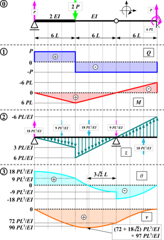
Direct integration is a structural analysis method for measuring internal shear, internal moment, rotation, and deflection of a beam.
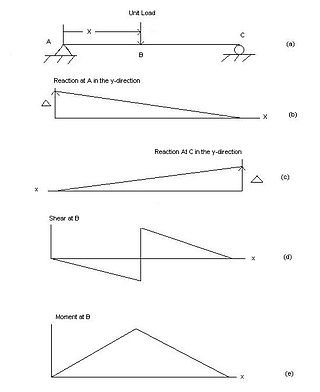
In engineering, an influence line graphs the variation of a function at a specific point on a beam or truss caused by a unit load placed at any point along the structure. Common functions studied with influence lines include reactions, shear, moment, and deflection (Deformation). Influence lines are important in designing beams and trusses used in bridges, crane rails, conveyor belts, floor girders, and other structures where loads will move along their span. The influence lines show where a load will create the maximum effect for any of the functions studied.
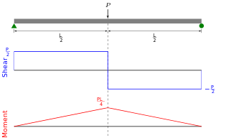
Shear force and bending moment diagrams are analytical tools used in conjunction with structural analysis to help perform structural design by determining the value of shear forces and bending moments at a given point of a structural element such as a beam. These diagrams can be used to easily determine the type, size, and material of a member in a structure so that a given set of loads can be supported without structural failure. Another application of shear and moment diagrams is that the deflection of a beam can be easily determined using either the moment area method or the conjugate beam method.

In structural engineering, deflection is the degree to which a part of a structural element is displaced under a load. It may refer to an angle or a distance.

Structural engineering depends upon a detailed knowledge of loads, physics and materials to understand and predict how structures support and resist self-weight and imposed loads. To apply the knowledge successfully structural engineers will need a detailed knowledge of mathematics and of relevant empirical and theoretical design codes. They will also need to know about the corrosion resistance of the materials and structures, especially when those structures are exposed to the external environment.
In civil engineering and structural analysis Clapeyron's theorem of three moments is a relationship among the bending moments at three consecutive supports of a horizontal beam.
The conjugate-beam methods is an engineering method to derive the slope and displacement of a beam. A conjugate beam is defined as an imaginary beam with the same dimensions (length) as that of the original beam but load at any point on the conjugate beam is equal to the bending moment at that point divided by EI.


