In civil engineering and structural analysisClapeyron's theorem of three moments is a relationship among the bending moments at three consecutive supports of a horizontal beam.
Let A,B,C-D be the three consecutive points of support, and denote by- l the length of AB and the length of BC, by w and the weight per unit of length in these segments. Then[1] the bending moments at the three points are related by:
where a1 is the area on the bending moment diagram due to vertical loads on AB, a2 is the area due to loads on BC, x1 is the distance from A to the centroid of the bending moment diagram of beam AB, x2 is the distance from C to the centroid of the area of the bending moment diagram of beam BC.
The second equation is more general as it does not require that the weight of each segment be distributed uniformly.
Figure 01-Sample continuous beam section
Derivation of three moments equations
Mohr's theorem[3] can be used to derive the three moment theorem[4] (TMT).
Mohr's first theorem
The change in slope of a deflection curve between two points of a beam is equal to the area of the M/EI diagram between those two points.(Figure 02)
Figure 02-Mohr's First Theorem
Mohr's second theorem
Consider two points k1 and k2 on a beam. The deflection of k1 and k2 relative to the point of intersection between tangent at k1 and k2 and vertical through k1 is equal to the moment of M/EI diagram between k1 and k2 about k1.(Figure 03)
Figure03-Mohr's Second Theorem
The three moment equation expresses the relation between bending moments at three successive supports of a continuous beam, subject to a loading on a two adjacent span with or without settlement of the supports.
The sign convention
According to the Figure 04,
The moment M1, M2, and M3 be positive if they cause compression in the upper part of the beam. (sagging positive)
The deflection downward positive. (Downward settlement positive)
Let ABC is a continuous beam with support at A,B, and C. Then moment at A,B, and C are M1, M2, and M3, respectively.
Let A' B' and C' be the final positions of the beam ABC due to support settlements.
Figure 04-Deflection Curve of a Continuous Beam Under Settlement
Derivation of three moment theorem
PB'Q is a tangent drawn at B' for final Elastic Curve A'B'C' of the beam ABC. RB'S is a horizontal line drawn through B'. Consider, Triangles RB'P and QB'S.
(1)
(2)
(3)
From (1), (2), and (3),
(a)
Draw the M/EI diagram to find the PA' and QC'.
Figure 05 - M / EI Diagram
From Mohr's Second Theorem PA' = First moment of area of M/EI diagram between A and B about A.
QC' = First moment of area of M/EI diagram between B and C about C.
Substitute in PA' and QC' on equation (a), the Three Moment Theorem (TMT) can be obtained.
Three moment equation
Notes
↑ J. B. Wheeler: An Elementary Course of Civil Engineering, 1876, Page 118
In mathematics, the Dirac delta distribution, also known as the unit impulse, is a generalized function or distribution over the real numbers, whose value is zero everywhere except at zero, and whose integral over the entire real line is equal to one.
A finite difference is a mathematical expression of the form f (x + b) − f (x + a). If a finite difference is divided by b − a, one gets a difference quotient. The approximation of derivatives by finite differences plays a central role in finite difference methods for the numerical solution of differential equations, especially boundary value problems.
Noether's theorem or Noether's first theorem states that every differentiable symmetry of the action of a physical system with conservative forces has a corresponding conservation law. The theorem was proven by mathematician Emmy Noether in 1915 and published in 1918. The action of a physical system is the integral over time of a Lagrangian function, from which the system's behavior can be determined by the principle of least action. This theorem only applies to continuous and smooth symmetries over physical space.
The moment of inertia, otherwise known as the mass moment of inertia, angular mass, second moment of mass, or most accurately, rotational inertia, of a rigid body is a quantity that determines the torque needed for a desired angular acceleration about a rotational axis, akin to how mass determines the force needed for a desired acceleration. It depends on the body's mass distribution and the axis chosen, with larger moments requiring more torque to change the body's rate of rotation.
In mathematics and physical science, spherical harmonics are special functions defined on the surface of a sphere. They are often employed in solving partial differential equations in many scientific fields.
Flight dynamics is the science of air vehicle orientation and control in three dimensions. The three critical flight dynamics parameters are the angles of rotation in three dimensions about the vehicle's center of gravity (cg), known as pitch, roll and yaw. These are collectively known as aircraft attitude, often principally relative to the atmospheric frame in normal flight, but also relative to terrain during takeoff or landing, or when operating at low elevation. The concept of attitude is not specific to fixed-wing aircraft, but also extends to rotary aircraft such as helicopters, and dirigibles, where the flight dynamics involved in establishing and controlling attitude are entirely different.
In vector calculus, Green's theorem relates a line integral around a simple closed curve C to a double integral over the plane region D bounded by C. It is the two-dimensional special case of Stokes' theorem.
In electrical engineering, the Y-Δ transform, also written wye-delta and also known by many other names, is a mathematical technique to simplify the analysis of an electrical network. The name derives from the shapes of the circuit diagrams, which look respectively like the letter Y and the Greek capital letter Δ. This circuit transformation theory was published by Arthur Edwin Kennelly in 1899. It is widely used in analysis of three-phase electric power circuits.
In mathematics, a Green's function is the impulse response of an inhomogeneous linear differential operator defined on a domain with specified initial conditions or boundary conditions.
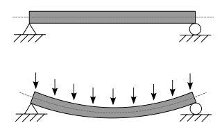
In applied mechanics, bending characterizes the behavior of a slender structural element subjected to an external load applied perpendicularly to a longitudinal axis of the element.
In physics, the Thomas precession, named after Llewellyn Thomas, is a relativistic correction that applies to the spin of an elementary particle or the rotation of a macroscopic gyroscope and relates the angular velocity of the spin of a particle following a curvilinear orbit to the angular velocity of the orbital motion.
Euler–Bernoulli beam theory is a simplification of the linear theory of elasticity which provides a means of calculating the load-carrying and deflection characteristics of beams. It covers the case corresponding to small deflections of a beam that is subjected to lateral loads only. By ignoring the effects of shear deformation and rotatory inertia, it is thus a special case of Timoshenko–Ehrenfest beam theory. It was first enunciated circa 1750, but was not applied on a large scale until the development of the Eiffel Tower and the Ferris wheel in the late 19th century. Following these successful demonstrations, it quickly became a cornerstone of engineering and an enabler of the Second Industrial Revolution.
Castigliano's method, named after Carlo Alberto Castigliano, is a method for determining the displacements of a linear-elastic system based on the partial derivatives of the energy. He is known for his two theorems. The basic concept may be easy to understand by recalling that a change in energy is equal to the causing force times the resulting displacement. Therefore, the causing force is equal to the change in energy divided by the resulting displacement. Alternatively, the resulting displacement is equal to the change in energy divided by the causing force. Partial derivatives are needed to relate causing forces and resulting displacements to the change in energy.
Macaulay’s method is a technique used in structural analysis to determine the deflection of Euler-Bernoulli beams. Use of Macaulay’s technique is very convenient for cases of discontinuous and/or discrete loading. Typically partial uniformly distributed loads (u.d.l.) and uniformly varying loads (u.v.l.) over the span and a number of concentrated loads are conveniently handled using this technique.
The moment distribution method is a structural analysis method for statically indeterminate beams and frames developed by Hardy Cross. It was published in 1930 in an ASCE journal. The method only accounts for flexural effects and ignores axial and shear effects. From the 1930s until computers began to be widely used in the design and analysis of structures, the moment distribution method was the most widely practiced method.
The slope deflection method is a structural analysis method for beams and frames introduced in 1914 by George A. Maney. The slope deflection method was widely used for more than a decade until the moment distribution method was developed. In the book, "The Theory and Practice of Modern Framed Structures", written by J.B Johnson, C.W. Bryan and F.E. Turneaure, it is stated that this method was first developed "by Professor Otto Mohr in Germany, and later developed independently by Professor G.A. Maney". According to this book, professor Otto Mohr introduced this method for the first time in his book, "Evaluation of Trusses with Rigid Node Connections" or "Die Berechnung der Fachwerke mit Starren Knotenverbindungen".
The Timoshenko–Ehrenfest beam theory was developed by Stephen Timoshenko and Paul Ehrenfest early in the 20th century. The model takes into account shear deformation and rotational bending effects, making it suitable for describing the behaviour of thick beams, sandwich composite beams, or beams subject to high-frequency excitation when the wavelength approaches the thickness of the beam. The resulting equation is of 4th order but, unlike Euler–Bernoulli beam theory, there is also a second-order partial derivative present. Physically, taking into account the added mechanisms of deformation effectively lowers the stiffness of the beam, while the result is a larger deflection under a static load and lower predicted eigenfrequencies for a given set of boundary conditions. The latter effect is more noticeable for higher frequencies as the wavelength becomes shorter, and thus the distance between opposing shear forces decreases.
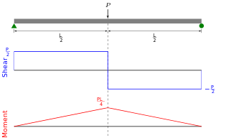
Shear force and bending moment diagrams are analytical tools used in conjunction with structural analysis to help perform structural design by determining the value of shear forces and bending moments at a given point of a structural element such as a beam. These diagrams can be used to easily determine the type, size, and material of a member in a structure so that a given set of loads can be supported without structural failure. Another application of shear and moment diagrams is that the deflection of a beam can be easily determined using either the moment area method or the conjugate beam method.
In structural engineering, deflection is the degree to which a part of a structural element is displaced under a load. It may refer to an angle or a distance.
In engineering, span is the distance between two intermediate supports for a structure, e.g. a beam or a bridge. A span can be closed by a solid beam or by a rope. The first kind is used for bridges, the second one for power lines, overhead telecommunication lines, some type of antennas or for aerial tramways.
This page is based on this Wikipedia article Text is available under the CC BY-SA 4.0 license; additional terms may apply. Images, videos and audio are available under their respective licenses.