A countersteam brake is a brake on a steam locomotive that uses the engine (specifically the cylinders) to help brake the locomotive.
A steam locomotive is a type of railway locomotive that produces its pulling power through a steam engine. These locomotives are fueled by burning combustible material – usually coal, wood, or oil – to produce steam in a boiler. The steam moves reciprocating pistons which are mechanically connected to the locomotive's main wheels (drivers). Both fuel and water supplies are carried with the locomotive, either on the locomotive itself or in wagons (tenders) pulled behind.

The cylinder is the power-producing element of the steam engine powering a steam locomotive. The cylinder is made pressure-tight with end covers and a piston; a valve distributes the steam to the ends of the cylinder. Cylinders were cast in cast iron and later in steel. The cylinder casting includes other features such as valve ports and mounting feet. The last big American locomotives incorporated the cylinders as part of huge one-piece steel castings that were the main frame of the locomotive. Renewable wearing surfaces were needed inside the cylinders and provided by cast-iron bushings.
It uses the working principle of steam cylinders fitted with slide or piston valves such that, by changing the configuration of the valve gear, the motion of the valves is also altered such that they work in opposition to the movement of the pistons.

The slide valve is a rectilinear valve used to control the admission of steam into, and emission of exhaust from, the cylinder of a steam engine.

Piston valves are one form of valve used to control the flow of steam within a steam engine or locomotive. They control the admission of steam into the cylinders and its subsequent exhausting, enabling a locomotive to move under its own power. The valve consists of two piston heads on a common spindle moving inside a steam chest, which is essentially a mini-cylinder located either above or below the main cylinders of the locomotive.

The valve gear of a steam engine is the mechanism that operates the inlet and exhaust valves to admit steam into the cylinder and allow exhaust steam to escape, respectively, at the correct points in the cycle. It can also serve as a reversing gear. It is sometimes referred to as the "motion".
Because of the inertia of a steam locomotive in its initial direction of travel, changing the direction in which the steam cylinders have to work acts first to brake the movement of the connecting rod, which in turn slows the transmission of power to the drive of the locomotive until it stops.

A connecting rod is a rigid member which connects a piston to a crank or crankshaft in a reciprocating engine. Together with the crank, it forms a simple mechanism that converts reciprocating motion into rotating motion.
The countersteam brake is often confused with the counterpressure brake, which works with air, not steam, and acts as a dynamic brake. Unlike the countersteam brake, the counterpressure brake is permitted to be used as an independent braking system in its own right.
Operation
The countersteam brake is actually not a brake in the true sense; but simply a way of using the working principle of a steam engine to produce a braking effect. It is therefore not a separate component of a steam locomotive. Countersteam braking is however only achievable with piston valves. On simple slide valves, no opposing steam admission is possible due to the way they are constructed.

A steam engine is a heat engine that performs mechanical work using steam as its working fluid. The steam engine uses the force produced by steam pressure to push a piston back and forth inside a cylinder. This pushing force is transformed, by a connecting rod and flywheel, into rotational force for work. The term "steam engine" is generally applied only to reciprocating engines as just described, not to the steam turbine.
Using the countersteam brake, experienced locomotive drivers can reverse the running direction of a steam locomotive almost as if it hasn't been brought to a stop, because the actual changeover point occurs whilst the locomotive is still moving in the initial direction of travel. This technique requires detailed knowledge and experience because if it is not carried out correctly, damage to the locomotive engine may result.
On steam locomotives without a second independent brake system (like e.g. a compressed-air brake, vacuum brake or steam brake) for the engine, in addition to the usual counterweight or fixed brake, the countersteam brake was used as a braking system. Today, steam locomotives generally have to have two independent brake systems in order to be licensed, so that the countersteam brake is not viewed as a braking system, but is nevertheless still used.
The vacuum brake is a braking system employed on trains and introduced in the mid-1860s. A variant, the automatic vacuum brake system, became almost universal in British train equipment and in countries influenced by British practice. Vacuum brakes also enjoyed a brief period of adoption in the United States, primarily on narrow-gauge railroads. Its limitations caused it to be progressively superseded by compressed air systems starting in the United Kingdom from the 1970s onward. The vacuum brake system is now obsolete; it is not in large-scale usage anywhere in the world, other than in South Africa, largely supplanted by air brakes.
A steam brake is a type of brake for steam locomotives and their tenders, whereby a steam cylinder works directly on the brake linkages.
This page is based on this
Wikipedia article Text is available under the
CC BY-SA 4.0 license; additional terms may apply.
Images, videos and audio are available under their respective licenses.

A reciprocating engine, also often known as a piston engine, is typically a heat engine that uses one or more reciprocating pistons to convert pressure into a rotating motion. This article describes the common features of all types. The main types are: the internal combustion engine, used extensively in motor vehicles; the steam engine, the mainstay of the Industrial Revolution; and the niche application Stirling engine. Internal combustion engines are further classified in two ways: either a spark-ignition (SI) engine, where the spark plug initiates the combustion; or a compression-ignition (CI) engine, where the air within the cylinder is compressed, thus heating it, so that the heated air ignites fuel that is injected then or earlier.
A railway air brake is a railway brake power braking system with compressed air as the operating medium. Modern trains rely upon a fail-safe air brake system that is based upon a design patented by George Westinghouse on April 13, 1869. The Westinghouse Air Brake Company was subsequently organized to manufacture and sell Westinghouse's invention. In various forms, it has been nearly universally adopted.

In internal combustion engines, variable valve timing (VVT) is the process of altering the timing of a valve lift event, and is often used to improve performance, fuel economy or emissions. It is increasingly being used in combination with variable valve lift systems. There are many ways in which this can be achieved, ranging from mechanical devices to electro-hydraulic and camless systems. Increasingly strict emissions regulations are causing many automotive manufacturers to use VVT systems.

This is a glossary of the components found on typical steam locomotives.
Engine braking occurs when the retarding forces within an engine are used to slow down a motor vehicle, as opposed to using additional external braking mechanisms such as friction brakes or magnetic brakes.

The Walschaerts valve gear is a type of valve gear invented by Belgian railway mechanical engineer Egide Walschaerts in 1844 used to regulate the flow of steam to the pistons in steam engines. The gear is sometimes named without the final "s", since it was incorrectly patented under that name. It was extensively used in steam locomotives from the late 19th century until the end of the steam era.
In a steam engine, cutoff is the point in the piston stroke at which the inlet valve is closed. On a steam locomotive, the cutoff is controlled by the reversing gear.
The uniflow type of steam engine uses steam that flows in one direction only in each half of the cylinder. Thermal efficiency is increased in the compound and multiple expansion types of steam engine by separating expansion into steps in separate cylinders; in the uniflow design, thermal efficiency is achieved by having a temperature gradient along the cylinder. Steam always enters at the hot ends of the cylinder and exhausts through ports at the cooler centre. By this means, the relative heating and cooling of the cylinder walls is reduced.

An expansion valve is a device in steam engine valve gear that improves engine efficiency. It operates by closing off the supply of steam early, before the piston has travelled through its full stroke. This cut-off allows the steam to then expand within the cylinder. This expanding steam is still sufficient to drive the piston, even though its pressure decreases as it expands. As less steam is supplied in the shorter time for which the valve is open, use of the expansion valve reduces the steam consumed and thus the fuel required. The engine may deliver two-thirds of the work, for only one-third of the steam.

A vacuum engine derives its force from air pressure against one side of the piston, which has a partial vacuum on the other side of it. At the beginning of an outstroke, a valve in the head of the cylinder opens and admits a charge of burning gas and air, which is trapped by the closing of the valve and expands. Towards the end of the stroke the charge comes into contact with a water- or air-cooled part of the cylinder and is chilled, causing a sudden drop in pressure sufficient to suck the piston – which is open towards the crank – back on the return stroke. The valve opens again in time for the piston to expel the burnt gases before the next outstroke begins.
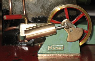
An oscillating cylinder steam engine is a simple steam-engine design that requires no valve gear. Instead the cylinder rocks, or oscillates, as the crank moves the piston, pivoting in the mounting trunnion so that ports in the cylinder line up with ports in a fixed port face alternately to direct steam into or out of the cylinder.
On a steam locomotive, the reversing gear is used to control the direction of travel of the locomotive. It also adjusts the cutoff of the steam locomotive.

The Trofimoff valve is a springless pressure-compensation piston valve for steam locomotives.

The Central South African Railways Rack 4-6-4RT of 1905 was a South African steam locomotive from the pre-Union era in Transvaal Colony.

The Willans engine or central valve engine was a high-speed stationary steam engine used for electricity generation around the start of the 20th century.