Air brake (road vehicle)

Last updated
Truck air-actuated disc brake Air disc brake.jpg
Truck air-actuated disc brake

An air brake or, more formally, a compressed-air-brake system, is a type of friction brake for vehicles in which compressed air pressing on a piston is used to both release the parking/emergency brakes in order to move the vehicle, and also to apply pressure to the brake pads or brake shoes to slow and stop the vehicle. Air brakes are used in large heavy vehicles, particularly those having multiple trailers which must be linked into the brake system, such as trucks, buses, trailers, and semi-trailers, in addition to their use in railroad trains. George Westinghouse first developed air brakes for use in railway service. [1] He patented a safer air brake on March 5, 1872. [2] [3] Westinghouse made numerous alterations to improve his air pressured brake invention, which led to various forms of the automatic brake. In the early 20th century, after its advantages were proven in railway use, it was adopted by manufacturers of trucks and heavy road vehicles.

Contents

Design and function

Air brakes are typically used on heavy trucks and buses. Typical operating pressure is approximately 100–120 psi or 690–830 kPa or 6.9–8.3 bar. A compressed-air-brake system is divided into a supply system and a control system.

The supply system compresses, stores and supplies high-pressure air to the control system as well as to additional air operated auxiliary truck systems (gearbox shift control, clutch pedal air assistance servo, etc.). The air compressor draws filtered air from the atmosphere and compresses it, storing the compressed air in high-pressure reservoirs. [4] Most heavy vehicles have a gauge within the driver's view, indicating the availability of air pressure for safe vehicle operation, often including warning tones or lights. A mechanical "wig wag" that automatically drops down into the driver's field of vision when the pressure drops below a certain point is also common.

The control system consists of service brakes, parking brakes, a control pedal, and an air storage tank. If the vehicle is towing a trailer, it often has a separate trailer-brake system that receives compressed air from the supply system.

The parking brakes use a disc or drum arrangement which is designed to be held in the 'applied' position by spring pressure. Air pressure must be produced to release these "spring brake" parking brakes. Setting the parking/emergency brake releases the pressurized air in the lines between the compressed air storage tank and the brakes, thus allowing the spring actuated parking brake to engage. A sudden loss of air pressure would result in full spring brake pressure immediately.

The service brakes are used while driving for slowing or stopping the vehicle. When the brake pedal is pushed to apply the service brakes, air is routed under pressure from a supply reservoir to the service brake chamber, causing the brake to be engaged. When the pedal is released, a return spring in the brake chamber disengages the brake, and the compressed air is exhausted to the atmosphere. [4] Most types of truck air brakes are drum brakes, though there is an increasing trend towards the use of disc brakes.

Supply system

Highly simplified air-brake diagram
Paineilmajarrut.svg
(does not show all air reservoirs and all applicable air valves)
1 Truck air compressor.jpg
Air compressor
 7 Park brake hand control.jpg
Park brake hand control valve
2Pressure regulator8Park brake safety release valve
3 Electronic air dryer.jpg
Air dryer
9 Air foot valve.jpg
Brake foot valve
4Regeneration reservoir10Front air-brake chambers
5 Four way protection valve.jpg
Four-way protection valve
11 Trailer brake relay valve.jpg
Brake-relay valve and load-sensing valve
6Compressed-air reservoirs12 Spring brake air cylinder.jpg
Rear-spring brake chambers

The air compressor (1) is driven by the engine either by crankshaft pulley via a belt or directly from the engine timing gears. Typically, it is lubricated and cooled by the engine lubrication and cooling systems, but some systems use self-lubricated compressors and/or air-cooled compressors. System pressure is regulated by a governor between a minimum and maximum value; [5] the governor unloads the compressor when the maximum system pressure has been achieved and loads the compressor when it falls below its minimum setpoint. [4] [6]

When the compressor is loaded, compressed air is first routed through a cooling coil and into an air dryer (3) which removes moisture and oil impurities and also may include a pressure regulator (2), safety valve and smaller purge reservoir (4). As an alternative to the air dryer, the supply system can be equipped with an anti-freeze device and oil separator.

The compressed air is then stored in a supply reservoir (6); the supply reservoir, which is physically closest to the compressor, is also called a wet tank because the majority of oil and water from the compressor gather here. A second, downstream reservoir is called the service reservoir, and forms the primary source for brake operation. [7] The supply and service reservoirs are sized to allow several service brake applications if the compressor fails or the engine stops. [4] From the service reservoir, compressed air is then distributed via a four-way protection valve (5) into the primary reservoir (rear brake reservoir) and the secondary reservoir (front/trailer-brake reservoir), a parking-brake reservoir, and an auxiliary air supply distribution point.

The supply system also includes various check, [8] pressure limiting, drain and safety valves. [9]

Control system

The control system is further divided into two service brake-circuits, the parking brake-circuit, and the trailer brake-circuit.

The dual-service brake circuits are further split into front- and rear-wheel circuits which receive compressed air from their individual supply reservoirs for added safety in case of an air leak. The service brakes are applied by means of a brake pedal air valve (9) which regulates both circuits. Depressing the brake pedal allows compressed air stored in the respective supply reservoirs to enter each service brake chamber (10) and (12), causing the service brakes to actuate. Releasing the brake pedal disconnects the supply reservoirs; a brake return spring forces the service brakes to release, and the compressed air that was used to actuate the service brakes is exhausted to the atmosphere. Repeated application of the service brakes will deplete the air reservoir pressure, prompting the governor to load the compressor again. [4] [6]

Relay valve(s) are used to improve brake response with long lines. Routing the lines for the rear and trailer service brakes through the brake pedal air valve could result in unacceptably slow actuation, so these brakes are plumbed directly to the service reservoir through a local relay valve (11) and the line from the brake pedal air valve is used to actuate the relay valve instead of the service brakes. [10] Similarly, quick-release valve(s) are located close to their respective brakes and allow the air to be exhausted more quickly when the brakes are released. [11]

The parking brake is the air operated spring brake type where the brake is applied by spring force in the spring brake cylinder (12) and released by compressed air via a hand-control valve (7).

The trailer brake consists of a direct two-line system: the supply line and the separate control or service line. The supply line receives air from the prime mover park brake air tank via a park brake relay valve and the control line is regulated via the trailer-brake relay valve. The operating signals for the relay are provided by the prime mover brake-pedal air valve, trailer service brake hand control (subject to local heavy vehicle legislation) and the prime mover park brake hand control.

Wig wag

Air-brake systems may include a wig wag device which deploys to warn the driver if the system air pressure drops too low.

Manual wig wag in warning position Wigwag.jpg
Manual wig wag in warning position

This device drops a mechanical arm into view when the pressure in the system drops below the threshold of sufficient pressure to reliably deploy the brakes. [12]

An automatic wig wag will rise out of view when the pressure in the system rises above the threshold. The manual-reset type must be placed in the out-of-view position manually. Neither will stay in place unless the pressure in the system is above the threshold. The photo to the left shows a manual wig wag which the operator swings to the right out of view when the air pressure is above the threshold where it will remain as long as the pressure is sufficient.

Most U.S. state commercial driver's license manuals, published by the states’ Departments of Motor Vehicles or equivalents, describe this term. [13]

Advantages

Air brakes are used as an alternative to hydraulic brakes which are used on lighter vehicles such as automobiles. Hydraulic brakes use a liquid (hydraulic fluid) to transfer pressure from the brake pedal to the brake shoe to stop the vehicle. Air brakes are used in heavy commercial vehicles due to their reliability. They have several advantages for large multi-trailer vehicles: [14]

Disadvantages

Although air brakes are considered the superior braking system for heavy vehicles (gross weight ~12 tonnes to 15 tonnes) which would overload hydraulic brakes, they also have the following disadvantages when compared to hydraulic braking systems:

See also

Related Research Articles

<span class="mw-page-title-main">Brake</span> Mechanical device that inhibits motion

A brake is a mechanical device that inhibits motion by absorbing energy from a moving system. It is used for slowing or stopping a moving vehicle, wheel, axle, or to prevent its motion, most often accomplished by means of friction.

<span class="mw-page-title-main">Railway air brake</span> Fail-safe power braking system with compressed air as the operating medium

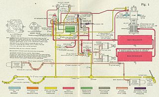
A railway air brake is a railway brake power braking system with compressed air as the operating medium. Modern trains rely upon a fail-safe air brake system that is based upon a design patented by George Westinghouse on April 13, 1869. The Westinghouse Air Brake Company was subsequently organized to manufacture and sell Westinghouse's invention. In various forms, it has been nearly universally adopted.

<span class="mw-page-title-main">Pneumatics</span> Branch of engineering

Pneumatics is a branch of engineering that makes use of gas or pressurized air.

<span class="mw-page-title-main">Automatic transmission</span> Type of motor vehicle transmission that automatically changes gear ratio as the vehicle moves

An automatic transmission is a multi-speed transmission used in motor vehicles that does not require any input from the driver to change forward gears under normal driving conditions. Vehicles with internal combustion engines, unlike electric vehicles, require the engine to operate in a narrow range of rates of rotation, requiring a gearbox, operated manually or automatically, to drive the wheels over a wide range of speeds.

<span class="mw-page-title-main">Fluid power</span> Use of fluids under pressure to generate, control, and transmit power

Fluid power is the use of fluids under pressure to generate, control, and transmit power. Fluid power is conventionally subdivided into hydraulics and pneumatics. Although steam is also a fluid, steam power is usually classified separately from fluid power. Compressed-air and water-pressure systems were once used to transmit power from a central source to industrial users over extended geographic areas; fluid power systems today are usually within a single building or mobile machine.

<span class="mw-page-title-main">Hydropneumatic suspension</span> Pneumatics

Hydropneumatic suspension is a type of motor vehicle suspension system, designed by Paul Magès, invented by Citroën, and fitted to Citroën cars, as well as being used under licence by other car manufacturers. Similar systems are also widely used on modern tanks and other large military vehicles. The suspension was referred to as suspension oléopneumatique in early literature, pointing to oil and air as its main components.

<span class="mw-page-title-main">Railway brake</span> Component of railway rolling stock

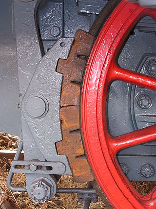
A railway brake is a type of brake used on the cars of railway trains to enable deceleration, control acceleration (downhill) or to keep them immobile when parked. While the basic principle is similar to that on road vehicle usage, operational features are more complex because of the need to control multiple linked carriages and to be effective on vehicles left without a prime mover. Clasp brakes are one type of brakes historically used on trains.

<span class="mw-page-title-main">Hydraulic machinery</span> Type of machine that uses liquid fluid power to perform work

Hydraulic machines use liquid fluid power to perform work. Heavy construction vehicles are a common example. In this type of machine, hydraulic fluid is pumped to various hydraulic motors and hydraulic cylinders throughout the machine and becomes pressurized according to the resistance present. The fluid is controlled directly or automatically by control valves and distributed through hoses, tubes, or pipes.

<span class="mw-page-title-main">Drive by wire</span> Automotive technology

Drive by wire or DbW technology in the automotive industry is the use of electronic or electro-mechanical systems in place of mechanical linkages that control driving functions. The concept is similar to fly-by-wire in the aviation industry. Drive-by-wire may refer to just the propulsion of the vehicle through electronic throttle control, or it may refer to electronic control over propulsion as well as steering and braking, which separately are known as steer by wire and brake by wire, along with electronic control over other vehicle driving functions.

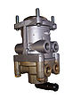
A relay valve is an air-operated valve typically used in air brake systems to remotely control the brakes at the rear of a heavy truck or semi-trailer in a tractor-trailer combination. Relay valves are necessary in heavy trucks in order to speed-up rear-brake application and release, since air takes longer to travel to the rear of the vehicle than the front of the vehicle, where the front service brakes, foot-valve, parking-control valve, and trailer-supply valve are located.

<span class="mw-page-title-main">Master cylinder</span> Control device that converts force into hydraulic pressure

In automotive engineering, the master cylinder is a control device that converts force into hydraulic pressure. This device controls slave cylinders located at the other end of the hydraulic brake system.

<span class="mw-page-title-main">Hydraulic brake</span> Arrangement of braking mechanism

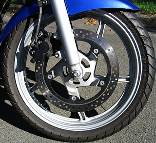
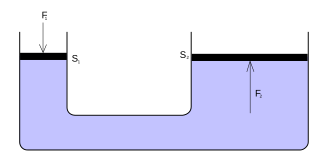
A hydraulic brake is an arrangement of braking mechanism which uses brake fluid, typically containing glycol ethers or diethylene glycol, to transfer pressure from the controlling mechanism to the braking mechanism.

<span class="mw-page-title-main">Parking brake</span> Secondary automotive braking system

In road vehicles, the parking brake, also known as a handbrake or emergency brake (e-brake), is a mechanism used to keep the vehicle securely motionless when parked. Parking brakes often consist of a pulling mechanism attached to a cable which is connected to two wheel brakes. In most vehicles, the parking brake operates only on the rear wheels, which have reduced traction while braking. The mechanism may be a hand-operated lever, a straight pull handle located near the steering column, or a foot-operated pedal located with the other pedals.

A pneumatic circuit is an interconnected set of components that convert compressed gas into mechanical work. In the normal sense of the term, the circuit must include a compressor or compressor-fed tank.

<span class="mw-page-title-main">Brake-by-wire</span> Automotive technology

Brake-by-wire technology in the automotive industry is the ability to control brakes through electronic means, without a mechanical connection that transfers force to the physical braking system from a driver input apparatus such as a pedal or lever.

A brake controller is usually an original equipment manufacturer or aftermarket-installed device or module. It is mounted to the tow vehicle's driver's-side dashboard area, and engages a trailer's electrical braking system either time delayed, or in proportion to the tow vehicle's brake engagement when slowing down or coming to a halt. A brake controller is not needed with a trailer surge braking system unless using modern electric over hydraulic devices. The trailer in this case usually has either electric friction brakes or electric-hydraulic trailer brake actuators.

<span class="mw-page-title-main">Line lock</span> Vehicle braking technology

A line lock is a device that allows the front brakes to lock independently of the rear brakes via a switch. The device is an electric solenoid that controls a valve which allows the brakes to be controlled individually. This allows the front brakes to be locked and the rear brakes to be open, and allows the driver to spin the rear wheels without wasting the rear brakes. This method is referred to as line lock and is popular among enthusiasts who like to do burnouts.

Sensotronic Brake Control (SBC) is an electro-hydraulic brake system, where the wheel brake cylinders on a vehicle are operated through a servomechanism.

Power brakes consist of a system of hydraulics used to slow down or stop a motor vehicle. It uses a combination of mechanical components and vacuum assistance to multiply the pressure applied to the brake pedal by the driver into enough force to actuate the brakes and stop the vehicle. By contrast, manual brakes rely solely on the pressure the driver applies to the brake pedal.

Jacobs Vehicle Systems, Inc. is an American company that engineers, develops and manufacturers commercial vehicle retarding and valve actuation technologies. The company produces light-duty, medium-duty, and heavy-duty engine brakes, recreational vehicle exhaust brakes, aftermarket parts and tune-up kits to heavy-duty diesel engine manufacturers in its domestic market in America, as well as in Asia and Europe. The company was incorporated in 1990 and is based in Bloomfield, Connecticut. Jacobs Vehicle Systems, Inc. operates as a subsidiary of Altra Industrial Motion Corporation. On 9 February 2022, Cummins, Inc. announced an agreement to acquire Jacobs Vehicle Systems from Altra.

References

  1. U.S. patent 88,929
  2. U.S. patent 124,404
  3. U.S. patent 124,405
  4. 1 2 3 4 5 "Basic system components". Saskatchewan Government Insurance. Retrieved 16 November 2021.
  5. "Air governor". Saskatchewan Government Insurance. Retrieved 16 November 2021.
  6. 1 2 "Basic air-brake system". Saskatchewan Government Insurance. Retrieved 16 November 2021.
  7. "Reservoir". Saskatchewan Government Insurance. Retrieved 16 November 2021.
  8. "One-way check valve". Saskatchewan Government Insurance. Retrieved 16 November 2021.
  9. "Safety valve". Saskatchewan Government Insurance. Retrieved 16 November 2021.
  10. "Relay valve". Saskatchewan Government Insurance. Retrieved 16 November 2021.
  11. "Quick-release valve". Saskatchewan Government Insurance. Retrieved 16 November 2021.
  12. "Wig Wag" . Retrieved December 4, 2014.
  13. "Wig Wag" (PDF). Retrieved December 4, 2014.
  14. Bennett, Sean (2010). Heavy Duty Truck Systems, 5th Ed. USA: Cengage Learning. p. 907. ISBN   978-1435483828.
  15. 1 2 3 Lyden, Sean. "Air Brakes or Hydraulic Brakes?". www.worktruckonline.com.
  16. https://www.fmcsa.dot.gov/content/38395 [ dead link ]
  17. Driving Commercial Vehicles: A Guide for Professional Drivers; page 1; ICBC; 2016; accessed 27 March 2019.
  18. "DOT 3 vs DOT 4 Brake Fluid" . Retrieved 16 April 2023.
  19. Stephen C Urman (1987). "A Survey of Railroad Occupational Noise Sources" (PDF). Transportation Research Board (1143): 22–25.
  20. "What Noises Cause Hearing Loss?". NCEH CDC. 7 October 2019.