Disk loading

Last updated
The MV-22 Osprey tiltrotor has a relatively high disk loading, producing visible blade tip vortices from condensation of the marine air in this photo of a vertical takeoff. MV-22B Osprey (USMC) 008.jpg
The MV-22 Osprey tiltrotor has a relatively high disk loading, producing visible blade tip vortices from condensation of the marine air in this photo of a vertical takeoff.
C-27J Spartan with propeller tip vortices condensation. The C-27J uses the same engines as the MV-22, but has higher disk loading. C27 Spartan making condensation spirals.jpg
C-27J Spartan with propeller tip vortices condensation. The C-27J uses the same engines as the MV-22, but has higher disk loading.
Piston-powered light utility helicopters like this Robinson R22 have relatively low main rotor disk loading. Flight.rob.arp.750pix.jpg
Piston-powered light utility helicopters like this Robinson R22 have relatively low main rotor disk loading.

In fluid dynamics, disk loading or disc loading is the average pressure change across an actuator disk, such as an airscrew. Airscrews with a relatively low disk loading are typically called rotors, including helicopter main rotors and tail rotors; propellers typically have a higher disk loading. [1] The V-22 Osprey tiltrotor aircraft has a high disk loading relative to a helicopter in the hover mode, but a relatively low disk loading in fixed-wing mode compared to a turboprop aircraft. [2]

Contents

Rotors

Disc loading of a hovering helicopter is the ratio of its weight to the total main rotor disc area. It is determined by dividing the total helicopter weight by the rotor disc area, which is the area swept by the blades of a rotor. Disc area can be found by using the span of one rotor blade as the radius of a circle and then determining the area the blades encompass during a complete rotation. When a helicopter is being maneuvered, its disc loading changes. The higher the loading, the more power needed to maintain rotor speed. [3] A low disc loading is a direct indicator of high lift thrust efficiency. [4]

Increasing the weight of a helicopter increases disk loading. For a given weight, a helicopter with shorter rotors will have higher disk loading, and will require more engine power to hover. A low disk loading improves autorotation performance in rotorcraft. [5] [6] Typically, an autogyro (or gyroplane) has a lower rotor disc loading than a helicopter, which provides a slower rate of descent in autorotation. [3]

Propellers

In reciprocating and propeller engines, disk loading can be defined as the ratio between propeller-induced velocity and freestream velocity.[ citation needed ] Lower disk loading will increase efficiency, so it is generally desirable to have larger propellers from an efficiency standpoint. Maximum efficiency is reduced as disk loading is increased due to the rotating slipstream; using contra-rotating propellers can alleviate this problem allowing high maximum efficiency even at relatively high disc loading. [7]

The Airbus A400M fixed-wing aircraft will have a very high disk loading on its propellers. [8]

Theory

The momentum theory or disk actuator theory describes a mathematical model of an ideal actuator disk, developed by W.J.M. Rankine (1865), Alfred George Greenhill (1888) and R.E. Froude (1889). The helicopter rotor is modeled as an infinitesimally thin disk with an infinite number of blades that induce a constant pressure jump over the disk area and along the axis of rotation. For a helicopter that is hovering, the aerodynamic force is vertical and exactly balances the helicopter weight, with no lateral force.

The downward force on the air flowing through the rotor is accompanied by an upward force on the helicopter rotor disk. The downward force produces a downward acceleration of the air, increasing its kinetic energy. This energy transfer from the rotor to the air is the induced power loss of the rotary wing, which is analogous to the lift-induced drag of a fixed-wing aircraft.

Conservation of linear momentum relates the induced velocity downstream in the far wake field to the rotor thrust per unit of mass flow. Conservation of energy considers these parameters as well as the induced velocity at the rotor disk. Conservation of mass relates the mass flow to the induced velocity. The momentum theory applied to a helicopter gives the relationship between induced power loss and rotor thrust, which can be used to analyze the performance of the aircraft. Viscosity and compressibility of the air, frictional losses, and rotation of the slipstream in the wake are not considered. [9]

Momentum theory

For an actuator disk of area , with uniform induced velocity at the rotor disk, and with as the density of air, the mass flow rate through the disk area is:

By conservation of mass, the mass flow rate is constant across the slipstream both upstream and downstream of the disk (regardless of velocity). Since the flow far upstream of a helicopter in a level hover is at rest, the starting velocity, momentum, and energy are zero. If the homogeneous slipstream far downstream of the disk has velocity , by conservation of momentum the total thrust developed over the disk is equal to the rate of change of momentum, which assuming zero starting velocity is:

By conservation of energy, the work done by the rotor must equal the energy change in the slipstream:

Substituting for and eliminating terms, we get:

So the velocity of the slipstream far downstream of the disk is twice the velocity at the disk, which is the same result as for an elliptically loaded wing predicted by lifting-line theory. [9]

Bernoulli's principle

To compute the disk loading using Bernoulli's principle, we assume the pressure in the slipstream far downstream is equal to the starting pressure , which is equal to the atmospheric pressure. From the starting point to the disk we have:

Between the disk and the distant wake, we have:

Combining equations, the disk loading is:

The total pressure in the distant wake is:

So the pressure change across the disk is equal to the disk loading. Above the disk the pressure change is:

Below the disk, the pressure change is:

The pressure along the slipstream is always falling downstream, except for the positive pressure jump across the disk. [9]

Power required

From the momentum theory, thrust is:

The induced velocity is:

Where is the disk loading as before, and the power required in hover (in the ideal case) is:

Therefore, the induced velocity can be expressed as:

So, the induced velocity is inversely proportional to the power loading . [10]

Examples

Correlation between disk loading and hover lift efficiency, for various VTOL aircraft VTOL DiscLoad-LiftEfficiency.svg
Correlation between disk loading and hover lift efficiency, for various VTOL aircraft
Disk loading comparison
AircraftDescriptionMax. gross weightTotal disk areaMax. disk loading
Robinson R22 Light utility helicopter 1,370 lb (635 kg)497 ft2 (46.2 m2)2.6 lb/ft2 (14 kg/m2)
Bell 206B3 JetRanger Turboshaft utility helicopter 3,200 lb (1,451 kg)872 ft2 (81.1 m2)3.7 lb/ft2 (18 kg/m2)
CH-47D Chinook Tandem rotor helicopter 50,000 lb (22,680 kg)5,655 ft2 (526 m2)8.8 lb/ft2 (43 kg/m2)
Mil Mi-26 Heavy-lift helicopter 123,500 lb (56,000 kg)8,495 ft2 (789 m2)14.5 lb/ft2 (71 kg/m2)
CH-53E Super Stallion Heavy-lift helicopter 73,500 lb (33,300 kg)4,900 ft2 (460 m2)15 lb/ft2 (72 kg/m2)
MV-22B Osprey Tiltrotor V/STOL 60,500 lb (27,400 kg)2,268 ft2 (211.4 m2)26.68 lb/ft2 (129.63 kg/m2)

See also

Related Research Articles

<span class="mw-page-title-main">Steam turbine</span> Machine that uses steam to rotate a shaft

A steam turbine is a machine that extracts thermal energy from pressurized steam and uses it to do mechanical work on a rotating output shaft. Its modern manifestation was invented by Charles Parsons in 1884. Fabrication of a modern steam turbine involves advanced metalwork to form high-grade steel alloys into precision parts using technologies that first became available in the 20th century; continued advances in durability and efficiency of steam turbines remains central to the energy economics of the 21st century.

<span class="mw-page-title-main">Thrust</span> Reaction force

Thrust is a reaction force described quantitatively by Newton's third law. When a system expels or accelerates mass in one direction, the accelerated mass will cause a force of equal magnitude but opposite direction to be applied to that system. The force applied on a surface in a direction perpendicular or normal to the surface is also called thrust. Force, and thus thrust, is measured using the International System of Units (SI) in newtons, and represents the amount needed to accelerate 1 kilogram of mass at the rate of 1 meter per second per second. In mechanical engineering, force orthogonal to the main load is referred to as static thrust.

<span class="mw-page-title-main">Navier–Stokes equations</span> Equations describing the motion of viscous fluid substances

The Navier–Stokes equations are partial differential equations which describe the motion of viscous fluid substances, named after French engineer and physicist Claude-Louis Navier and Irish physicist and mathematician George Gabriel Stokes. They were developed over several decades of progressively building the theories, from 1822 (Navier) to 1842-1850 (Stokes).

<span class="mw-page-title-main">Bernoulli's principle</span> Principle relating to fluid dynamics

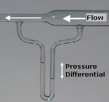
Bernoulli's principle is a key concept in fluid dynamics that relates pressure, speed and height. Bernoulli's principle states that an increase in the speed of a fluid occurs simultaneously with a decrease in static pressure or the fluid's potential energy. The principle is named after the Swiss mathematician and physicist Daniel Bernoulli, who published it in his book Hydrodynamica in 1738. Although Bernoulli deduced that pressure decreases when the flow speed increases, it was Leonhard Euler in 1752 who derived Bernoulli's equation in its usual form.

<span class="mw-page-title-main">Boundary layer</span> Layer of fluid in the immediate vicinity of a bounding surface

In physics and fluid mechanics, a boundary layer is the thin layer of fluid in the immediate vicinity of a bounding surface formed by the fluid flowing along the surface. The fluid's interaction with the wall induces a no-slip boundary condition. The flow velocity then monotonically increases above the surface until it returns to the bulk flow velocity. The thin layer consisting of fluid whose velocity has not yet returned to the bulk flow velocity is called the velocity boundary layer.

Blade element theory (BET) is a mathematical process originally designed by William Froude (1878), David W. Taylor (1893) and Stefan Drzewiecki (1885) to determine the behavior of propellers. It involves breaking a blade down into several small parts then determining the forces on each of these small blade elements. These forces are then integrated along the entire blade and over one rotor revolution in order to obtain the forces and moments produced by the entire propeller or rotor. One of the key difficulties lies in modelling the induced velocity on the rotor disk. Because of this the blade element theory is often combined with momentum theory to provide additional relationships necessary to describe the induced velocity on the rotor disk, producing blade element momentum theory. At the most basic level of approximation a uniform induced velocity on the disk is assumed:

<span class="mw-page-title-main">Momentum theory</span> Mathematical model in fluid dynamics

In fluid dynamics, momentum theory or disk actuator theory is a theory describing a mathematical model of an ideal actuator disk, such as a propeller or helicopter rotor, by W.J.M. Rankine (1865), Alfred George Greenhill (1888) and Robert Edmund Froude (1889).

<span class="mw-page-title-main">Ram pressure</span> Pressure due to movement through a fluid medium

Ram pressure is a pressure exerted on a body moving through a fluid medium, caused by relative bulk motion of the fluid rather than random thermal motion. It causes a drag force to be exerted on the body. Ram pressure is given in tensor form as

In fluid dynamics, drag is a force acting opposite to the relative motion of any object moving with respect to a surrounding fluid. This can exist between two fluid layers or between a fluid and a solid surface.

In fluid mechanics, added mass or virtual mass is the inertia added to a system because an accelerating or decelerating body must move some volume of surrounding fluid as it moves through it. Added mass is a common issue because the object and surrounding fluid cannot occupy the same physical space simultaneously. For simplicity this can be modeled as some volume of fluid moving with the object, though in reality "all" the fluid will be accelerated, to various degrees.

In physics and fluid mechanics, a Blasius boundary layer describes the steady two-dimensional laminar boundary layer that forms on a semi-infinite plate which is held parallel to a constant unidirectional flow. Falkner and Skan later generalized Blasius' solution to wedge flow, i.e. flows in which the plate is not parallel to the flow.

<span class="mw-page-title-main">Betz's law</span> Aerodynamic power limitation for wind turbines

In aerodynamics, Betz's law indicates the maximum power that can be extracted from the wind, independent of the design of a wind turbine in open flow. It was published in 1919 by the German physicist Albert Betz. The law is derived from the principles of conservation of mass and momentum of the air stream flowing through an idealized "actuator disk" that extracts energy from the wind stream. According to Betz's law, no aerodynamically thin windmill of any mechanism can capture more than 16/27 (59.3%) of the kinetic energy in wind. The factor 16/27 (0.593) is known as Betz's coefficient. Practical utility-scale wind turbines achieve at peak 75–80% of the Betz limit.

In fluid dynamics, Airy wave theory gives a linearised description of the propagation of gravity waves on the surface of a homogeneous fluid layer. The theory assumes that the fluid layer has a uniform mean depth, and that the fluid flow is inviscid, incompressible and irrotational. This theory was first published, in correct form, by George Biddell Airy in the 19th century.

In fluid dynamics the Borda–Carnot equation is an empirical description of the mechanical energy losses of the fluid due to a (sudden) flow expansion. It describes how the total head reduces due to the losses. This is in contrast with Bernoulli's principle for dissipationless flow, where the total head is a constant along a streamline. The equation is named after Jean-Charles de Borda (1733–1799) and Lazare Carnot (1753–1823).

<span class="mw-page-title-main">Wind-turbine aerodynamics</span> Physical property

The primary application of wind turbines is to generate energy using the wind. Hence, the aerodynamics is a very important aspect of wind turbines. Like most machines, wind turbines come in many different types, all of them based on different energy extraction concepts.

<span class="mw-page-title-main">Advance ratio</span> Ratio of freestream speed to tip speed

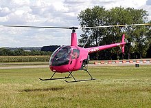
In aeronautics and marine hydrodynamics, the advance ratio is the ratio of the freestream fluid speed to the propeller, rotor, or cyclorotor tip speed. When a propeller-driven vehicle is moving at high speed relative to the fluid, or the propeller is rotating slowly, the advance ratio of its propeller(s) is a high number. When the vehicle is moving at low speed or the propeller is rotating at high speed, the advance ratio is a low number. The advance ratio is a useful non-dimensional quantity in helicopter and propeller theory, since propellers and rotors will experience the same angle of attack on every blade airfoil section at the same advance ratio regardless of actual forward speed. It is the inverse of the tip speed ratio used for wind turbines.

In fluid mechanics, dynamic similarity is the phenomenon that when there are two geometrically similar vessels with the same boundary conditions and the same Reynolds and Womersley numbers, then the fluid flows will be identical. This can be seen from inspection of the underlying Navier-Stokes equation, with geometrically similar bodies, equal Reynolds and Womersley Numbers the functions of velocity (u’,v’,w’) and pressure (P’) for any variation of flow.

Blade element momentum theory is a theory that combines both blade element theory and momentum theory. It is used to calculate the local forces on a propeller or wind-turbine blade. Blade element theory is combined with momentum theory to alleviate some of the difficulties in calculating the induced velocities at the rotor.

An axial fan is a type of fan that causes gas to flow through it in an axial direction, parallel to the shaft about which the blades rotate. The flow is axial at entry and exit. The fan is designed to produce a pressure difference, and hence force, to cause a flow through the fan. Factors which determine the performance of the fan include the number and shape of the blades. Fans have many applications including in wind tunnels and cooling towers. Design parameters include power, flow rate, pressure rise and efficiency.

Propeller theory is the science governing the design of efficient propellers. A propeller is the most common propulsor on ships, and on small aircraft.

References

  1. Stepniewski, W. Z.; Keys, C. N. (1984). Rotary-Wing Aerodynamics . New York: Dover Publications. p. 3. ISBN   0-486-64647-5. OCLC   565962623. It is interesting to note that there has always been a strong intuitive association of rotary-wing aircraft with low disc loading which is reflected in the commonly accepted name of rotor given to their lifting airscrews.
  2. Wang, James M.; Jones, Christopher T.; Nixon, Mark W. (1999-05-27). A Variable Diameter Short Haul Civil Tiltrotor. 55th Annual Forum of the American Helicopter Society. Montreal, Quebec, Canada. CiteSeerX   10.1.1.45.612 . The variable diameter tiltrotor (VDTR) is a Sikorsky concept aimed at improving tiltrotor hover and cruise performance currently limited by disk loading that is much higher in hover than conventional helicopter, and much lower in cruise than turbo-prop systems.
  3. 1 2 Rotorcraft Flying Handbook (PDF). U.S. Government Printing Office, Washington D.C.: U.S. Federal Aviation Administration. 2000. pp. 2–4, 19–3, G-2. FAA-8083-21. DISC LOADING—The total helicopter weight divided by the rotor disc area.
  4. Maisel, Martin D., Demo J. Giulianetti and Daniel C. Dugan. NASA SP-2000-4517, "The History of the XV-15 Tilt Rotor Research Aircraft: From Concept to Flight" (PDF) p2. NASA , 2000. Accessed: 17 March 2012.
  5. Noor, Ahmed Khairy (1996). Future Aeronautical and Space Systems (Progress in Astronautics and Aeronautics). AIAA (American Institute of Aeronautics & Astronautics). p. 66. ISBN   1-56347-188-4. Reduced disk loading in the vertical mode also results in lower downwash and improved capability for autorotation.
  6. Leishman, J. Gordon. "Development of the Autogiro : A Technical Perspective Archived 2005-12-31 at the Wayback Machine " page 5. Hofstra University , New York, 2003.
  7. Birdsall, David (1996). Aircraft Performance . Cambridge: Cambridge University Press. pp.  99. ISBN   0-521-56836-6. contra-rotating propellers this rotational loss can be eliminated and maximum efficiencies approaching 0.9 can be obtained even with high disc loading
  8. Reinhard Hilbig; Wagner, Siegfried; Ulrich Rist; Hans-Joachim Heinemann (2002). New Results in Numerical and Experimental Fluid Mechanics III. Notes on Numerical Fluid Mechanics and Multidisciplinary Design. Vol. 3. Berlin: Springer. p. 82. ISBN   3-540-42696-5. The A400M will be driven by four modern turboprop engines with a high disc loading.... The disc loading of the propellers is significantly higher than realised on former tactical transport aircraft like C130H or Transall C160.
  9. 1 2 3 Johnson, Wayne (1994). "2". Helicopter theory . New York: Dover Publications. pp.  28–34. ISBN   0-486-68230-7. In the momentum theory analysis the rotor is modeled as an actuator disk, which is a circular surface of zero thickness that can support a pressure difference and thus accelerate the air through the disk.
  10. Leishman, J. Gordon (2006). Principles of Helicopter Aerodynamics . Cambridge, UK: Cambridge University Press. ISBN   0-521-85860-7. OCLC   61463625.

PD-icon.svg This article incorporates public domain material from Rotorcraft Flying Handbook (PDF). Federal Aviation Administration.