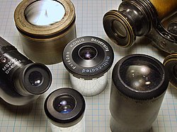
An eyepiece, or ocular lens, is a type of lens that is attached to a variety of optical devices such as telescopes and microscopes. It is named because it is usually the lens that is closest to the eye when someone looks through an optical device to observe an object or sample. The objective lens or mirror collects light from an object or sample and brings it to focus creating an image of the object. The eyepiece is placed near the focal point of the objective to magnify this image to the eyes. (The eyepiece and the eye together make an image of the image created by the objective, on the retina of the eye.) The amount of magnification depends on the focal length of the eyepiece.
An eyepiece consists of several "lens elements" in a housing, with a "barrel" on one end. The barrel is shaped to fit in a special opening of the instrument to which it is attached. The image can be focused by moving the eyepiece nearer and further from the objective. Most instruments have a focusing mechanism to allow movement of the shaft in which the eyepiece is mounted, without needing to manipulate the eyepiece directly.
The eyepieces of binoculars are usually permanently mounted in the binoculars, causing them to have a pre-determined magnification and field of view. With telescopes and microscopes, however, eyepieces are usually interchangeable. By switching the eyepiece, the user can adjust what is viewed. For instance, eyepieces will often be interchanged to increase or decrease the magnification of a telescope. Eyepieces also offer varying fields of view, and differing degrees of eye relief for the person who looks through them.
Properties
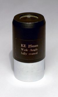
A 25mm Kellner eyepiece
Several properties of an eyepiece are likely to be of interest to a user of an optical instrument, when comparing eyepieces and deciding which eyepiece suits their needs.
Design distance to entrance pupil
Eyepieces are optical systems where the entrance pupil is invariably located outside of the system. They must be designed for optimal performance for a specific distance to this entrance pupil (i.e. with minimum aberrations for this distance). In a refracting astronomical telescope the entrance pupil is identical with the objective. This may be several feet distant from the eyepiece; whereas with a microscope eyepiece the entrance pupil is close to the back focal plane of the objective, mere inches from the eyepiece. Microscope eyepieces may be corrected differently from telescope eyepieces; however, most are also suitable for telescope use.
Elements and groups
Elements are the individual lenses, which may come as simple lenses or "singlets" and cemented doublets or (rarely) triplets. When lenses are cemented together in pairs or triples, the combined elements are called groups (of lenses).
The first eyepieces had only a single lens element, which delivered highly distorted images. Two and three-element designs were invented soon after, and quickly became standard due to the improved image quality. Today, engineers assisted by computer-aided drafting software have designed eyepieces with seven or eight elements that deliver exceptionally large, sharp views.
Internal reflection and scatter
Internal reflections, sometimes called "scatter", cause the light passing through an eyepiece to disperse and reduce the contrast of the image projected by the eyepiece. When the effect is particularly bad, "ghost images" are seen, called "ghosting". For many years, simple eyepiece designs with a minimum number of internal air-to-glass surfaces were preferred to avoid this problem.
One solution to scatter is to use thin film coatings over the surface of the element. These thin coatings are only one or two wavelengths deep, and work to reduce reflections and scattering by changing the refraction of the light passing through the element. Some coatings may also absorb light that is not being passed through the lens in a process called total internal reflection where the light incident on the film is at a shallow angle.
Chromatic aberration
Comparison of an ideal image of a ring (1) and ones with only axial (2) and only transverse (3) chromatic aberration
Lateral or transversechromatic aberration is caused because the refraction at glass surfaces differs for light of different wavelengths. Blue light, seen through an eyepiece element, will not focus to the same point but along the same axis as red light. The effect can create a ring of false colour around point sources of light and results in a general blurriness to the image.
One solution is to reduce the aberration by using multiple elements of different types of glass. Achromats are lens groups that bring two different wavelengths of light to the same focus and exhibit greatly reduced false colour. Low dispersion glass may also be used to reduce chromatic aberration.
Longitudinal chromatic aberration is a pronounced effect of optical telescope objectives, because the focal lengths are so long. Microscopes, whose focal lengths are generally shorter, do not tend to suffer from this effect.
Focal length
The focal length of an eyepiece is the distance from the principal plane of the eyepiece to where parallel rays of light converge to a single point. When in use, the focal length of an eyepiece, combined with the focal length of the telescope or microscope objective, to which it is attached, determines the magnification. It is usually expressed in millimetres when referring to the eyepiece alone. When interchanging a set of eyepieces on a single instrument, however, some users prefer to identify each eyepiece by the magnification produced.
For a telescope, the approximate angular magnification produced by the combination of a particular eyepiece and objective can be calculated with the following formula:
where:
is the focal length of the objective,
is the focal length of the eyepiece.
Magnification increases, therefore, when the focal length of the eyepiece is shorter or the focal length of the objective is longer. For example, a 25mm eyepiece in a telescope with a 1200mm focal length would magnify objects 48times. A 4mm eyepiece in the same telescope would magnify 300times.
Amateur astronomers tend to refer to telescope eyepieces by their focal length in millimeters. These typically range from about 3mm to 50mm. Some astronomers, however, prefer to specify the resulting magnification power rather than the focal length. It is often more convenient to express magnification in observation reports, as it gives a more immediate impression of what view the observer actually saw. Due to its dependence on properties of the particular telescope in use, however, magnification power alone is meaningless for describing a telescope eyepiece.
For a compound microscope the corresponding formula is
is the distance between the back focal plane of the objective and the back focal plane of the eyepiece (loosely called the "tube length"), typically 160mm for a modern instrument.
is the objective focal length and is the eyepiece focal length.
By convention, microscope eyepieces are usually specified by power instead of focal length. Microscope eyepiece power and objective power are defined by
thus from the expression given earlier for the angular magnification of a compound microscope
The total angular magnification of a microscope image is then simply calculated by multiplying the eyepiece power by the objective power. For example, a 10× eyepiece with a 40× objective will magnify the image 400times.
This definition of lens power relies upon an arbitrary decision to split the angular magnification of the instrument into separate factors for the eyepiece and the objective. Historically, Abbe described microscope eyepieces differently, in terms of angular magnification of the eyepiece and 'initial magnification' of the objective. While convenient for the optical designer, this turned out to be less convenient from the viewpoint of practical microscopy and was thus subsequently abandoned.
The generally accepted visual distance of closest focus is 250mm, and eyepiece power is normally specified assuming this value. Common eyepiece powers are 8×, 10×, 15×, and 20×. The focal length of the eyepiece (in mm) can thus be determined if required by dividing 250mm by the eyepiece power.
Modern instruments often use objectives optically corrected for an infinite tube length rather than 160mm, and these require an auxiliary correction lens in the tube.
Location of focal plane
In some eyepiece types, such as Ramsden eyepieces (described in more detail below), the eyepiece behaves as a magnifier, and its focal plane is located outside of the eyepiece in front of the field lens. This plane is therefore accessible as a location for a graticule or micrometer crosswires. In the Huygenian eyepiece,[1] the focal plane is located between the eye and field lenses, inside the eyepiece, and is hence not accessible.
Simulation of views through a telescope using different eyepieces. The center image uses an eyepiece of the same focal length as the one on the left, but has a wider apparent field of view giving a larger image that shows more area. The image on the right has the same apparent field of view as the center eyepiece but has a shorter focal length, giving the same true field of view as the left image but at higher magnification.The Plössl, an eyepiece with a large apparent field of view
The field of view, often abbreviated FOV, describes the area of a target (measured as an angle from the location of viewing) that can be seen when looking through an eyepiece. The field of view seen through an eyepiece varies, depending on the magnification achieved when connected to a particular telescope or microscope, and also on properties of the eyepiece itself. Eyepieces are differentiated by their field stop, which is the narrowest aperture that light entering the eyepiece must pass through to reach the field lens of the eyepiece.
Due to the effects of these variables, the term "field of view" nearly always refers to one of two meanings:
True or Telescope's field of view
For a telescope or binocular, the actual angular size of the span of sky that can be seen through a particular eyepiece, used with a particular telescope, producing a specific magnification. It ranges typically between 0.1–2degrees. For a microscope, the actual width of the visible sample on the slide or sample tray, usually given in millimeters, but sometimes given as angular measure, like a telescope. For binoculars it is expressed as the actual field width in feet or in meters at some standard distance (typically either 100feet or 30meters, which are very nearly the same: 30m is only a 2% smaller than 100feet).
Apparent or Eye's field of view
For telescopes, microscopes, or binoculars, the apparent field of view is a measure of the angular size of the image seen by the eye, through the eyepiece. In other words, it is how large the image appears (as distinct from the magnification). Unless there is vignetting by the telescope's or microscope's body tube, this is constant for any given eyepiece with a fixed focal length, and may be used to calculate what the true field of view will be when the eyepiece is used with a given telescope or microscope. For modern eyepieces, the measurement ranges from 30–110degrees, with all current good eyepieces being at least 50°, except for a few special-purpose eyepieces, such as some equipped with reticles.
It is common for users of an eyepiece to want to calculate the actual field of view, because it indicates how much of the sky will be visible when the eyepiece is used with their telescope. The most convenient method of calculating the actual field of view depends on whether the apparent field of view is known.
If the apparent field of view is known, the actual field of view can be calculated from the following approximate formula:
where:
is the true field of view (on the sky), calculated in whichever unit of angular measurement that is provided in;
is the apparent field of view (in the eye);
is the magnification.
The formula is accurate to 4% or better up to 40° apparent field of view, and has a 10% error for 60°.
Since where:
is the focal length of the telescope;
is the focal length of the eyepiece, expressed in the same units of measurement as
The true field of view even without knowing the apparent field of view, given by:
The focal length of the telescope objective, is the diameter of the objective times the focal ratio. It represents the distance at which the mirror or objective lens will cause light from a star to converge onto a single point (aberrations excepted).
If the apparent field of view is unknown, the actual field of view can be approximately found using:
where:
is the actual field of view, calculated in degrees.
is the diameter of the eyepiece field stop in mm.
is the focal length of the telescope, in mm.
The second formula is actually more accurate, but field stop size is not usually specified by most manufacturers. The first formula will not be accurate if the field is not flat, or is higher than 60° which is common for most ultra-wide eyepiece design.
The above formulas are approximations. The ISO 14132-1:2002 standard gives the exact calculation for apparent field of view, from the true field of view, as:
If a diagonal or Barlow lens is used before the eyepiece, the eyepiece's field of view may be slightly restricted. This occurs when the preceding lens has a narrower field stop than the eyepiece's, causing the obstruction in the front to act as a smaller field stop in front of the eyepiece. The exact relationship is given by
An occasionally used approximation is
This formula also indicates that, for an eyepiece design with a given apparent field of view, the barrel diameter will determine the maximum focal length possible for that eyepiece, as no field stop can be larger than the barrel itself. For example, a Plössl with 45° apparent field of view in a 1.25inch barrel would yield a maximum focal length of 35mm.[2] Anything longer requires larger barrel or the view is restricted by the edge, effectively making the field of view less than 45°.
Barrel diameter
Eyepieces for telescopes and microscopes are usually interchanged to increase or decrease the magnification, and to enable the user to select a type with certain performance characteristics. To allow this, eyepieces come in standardized "Barrel diameters".
Telescope eyepieces
Examples (from left to right) of 2″ (51mm), 1.25″ (32mm), and 0.965″ (24.5mm) eyepieces.
There are six standard barrel diameters for telescopes. The barrel sizes (usually expressed in inches[citation needed]) are:
0.965inch (24.5mm) – This is the smallest standard barrel diameter and is usually found in retail toy store and shopping mall telescopes. Many of these eyepieces that come with such telescopes are plastic, and some even have plastic lenses. High-end telescope eyepieces with this barrel size are no longer manufactured, but you can still purchase Kellner types.
1.25inch (31.75mm) – This is the most popular telescope eyepiece barrel diameter. The practical upper limit on focal lengths for eyepieces with 1.25″ barrels is about 32mm. With longer focal lengths, the edges of the eyepiece barrel intrude into the view, limiting its size. With focal lengths longer than 32mm, the available field of view falls below 50°, which most amateurs consider to be the minimum acceptable width. These barrel sizes are threaded for 30mm filters.
2inch (50.8mm) – The larger barrel size in 2″ eyepieces helps alleviate the limit on focal lengths; it is the largest size commonly available. The upper limit of focal length with 2″ eyepieces is about 55mm. The trade-off is that these eyepieces are usually more expensive, will not fit in some telescopes, and may be heavy enough to tip the telescope. These barrel sizes are threaded for 48mm filters (or rarely 49mm).
2.7inch (68.58mm) – 2.7″ eyepieces are only made by a few manufacturers. They allow for slightly larger fields of view. Many high-end focusers now accept these eyepieces.
3inch (76.2mm) – The even larger barrel size in 3″ eyepieces allows for extreme focal lengths and over 120° field of view eyepieces. The disadvantages are that these eyepieces are somewhat rare, extremely expensive, up to 5lbs in weight, and that only a few telescopes have focusers large enough to accept them. Their huge weight causes balancing issues in Schmidt-Cassegrains under 10inches, refractors under 5inches, and reflectors under 16inches. Also, due to their large field stops, without large-diameter secondary mirrors, most reflectors and Schmidt-Cassegrains will have severe vignetting with these eyepieces.[b]
4inch (102mm) – Eyepieces this size are rare, and only commonly used for long refracting telescopes in older observatories. Very few manufacturers make them, and with the current popularity of short focal length / smaller focal ratio telescopes among amateurs, the demand for this size is low. They are sometimes improvised from re‑adapted lenses scavenged out of old cinema projectors.
Microscope eyepieces
Eyepieces for microscopes have a variety of barrel diameters, usually given in millimeters, such as 23.2mm and 30mm.
Eye relief
The eye relief: 1Real image; 2field diaphragm; 3eye relief; 4exit pupil. The eyepiece is an Abbe ("ortho") design.
The eye needs to be held at a certain distance behind the eye lens of an eyepiece to see images properly through it. This distance is called the eye relief. A larger eye relief means that the optimum position is farther from the eyepiece, making it easier to view an image. However, if the eye relief is too large it can be uncomfortable to hold the eye in the correct position for an extended period of time, for which reason some eyepieces with long eye relief have cups behind the eye lens to aid the observer in maintaining the correct observing position. The eye pupil should coincide with the exit pupil, the image of the entrance pupil, which in the case of an astronomical telescope corresponds to the object glass.
Eye relief typically ranges from about 2mm to 20mm, depending on the construction of the eyepiece. Long focal-length eyepieces usually have ample eye relief, but short focal-length eyepieces are more problematic. Until recently, and still quite commonly, eyepieces of a short-focal length have had a short eye relief. Good design guidelines suggest a minimum of 5–6mm to accommodate the eyelashes of the observer to avoid discomfort. Modern designs with many lens elements, however, can correct for this, and viewing at high power becomes more comfortable. This is especially the case for spectacle wearers, who may need up to 20mm of eye relief to accommodate their glasses.
Designs
Technology has developed over time and there are a variety of eyepiece designs for use with telescopes, microscopes, gun-sights, and other devices. Some of these designs are described in more detail below.
Negative lens or "Galilean"
Negative lens
The simple negative lens placed before the focus of the objective has the advantage of presenting an erect image but with limited field of view better suited to low magnification. It is suspected this type of lens was used in some of the first refracting telescopes that appeared in the Netherlands in about 1608. It was also used in Galileo Galilei's 1609 telescope design which gave this type of eyepiece arrangement the name "Galilean". This type of eyepiece is still used in very cheap telescopes, binoculars and in opera glasses.
Convex lens
Convex lens
A simple convex lens placed after the focus of the objective lens presents the viewer with a magnified inverted image. This configuration may have been used in the first refracting telescopes from the Netherlands and was proposed as a way to have a much wider field of view and higher magnification in telescopes in Johannes Kepler's 1611 book Dioptrice. Since the lens is placed after the focal plane of the objective it also allowed for use of a micrometer at the focal plane (used for determining the angular size and/or distance between objects observed).
Huygens
Huygens eyepiece diagram
Huygens eyepieces consist of two plano-convex lenses with the plane sides towards the eye separated by an air gap. The lenses are called the eye lens and the field lens. The focal plane is located between the two lenses. It was invented by Christiaan Huygens in the late 1660s and was the first compound (multi-lens) eyepiece.[3] Huygens discovered that two air spaced lenses can be used to make an eyepiece with zero transverse chromatic aberration. If the lenses are made of glass of the same Abbe number, to be used with a relaxed eye and a telescope with an infinitely distant objective then the separation is given by:
where and are the focal lengths of the component lenses.
These eyepieces work well with the very long focal length telescopes.[c] This optical design is now considered obsolete since with today's shorter focal length telescopes the eyepiece suffers from short eye relief, high image distortion, axial chromatic aberration, and a very narrow apparent field of view. Since these eyepieces are cheap to make they can often be found on inexpensive telescopes and microscopes.[4]
Because Huygens eyepieces do not contain cement to hold the lens elements, telescope users sometimes use these eyepieces in the role of "solar projection", i.e. projecting an image of the Sun onto a screen for prolonged periods of time. Cemented eyepieces are traditionally regarded as potentially vulnerable to heat damage by the intense concentrations of light involved.
Ramsden
Ramsden eyepiece diagram
The Ramsden eyepiece comprises two plano-convex lenses of the same glass and similar focal lengths, placed less than one eye-lens focal length apart, a design created by astronomical and scientific instrument maker Jesse Ramsden in 1782. The lens separation varies between different designs, but is typically somewhere between 7 /10 and 7 /8 of the focal length of the eye-lens, the choice being a trade off between residual transverse chromatic aberration (at low values) and at high values running the risk of the field lens touching the focal plane when used by an observer who works with a close virtual image such as a myopic observer, or a young person whose accommodation is able to cope with a close virtual image (this is a serious problem when used with a micrometer as it can result in damage to the instrument).
A separation of exactly 1 focal length is also inadvisable since it renders the dust on the field lens disturbingly in focus. The two curved surfaces face inwards. The focal plane is thus located outside of the eyepiece and is hence accessible as a location where a graticule, or micrometer crosshairs may be placed. Because a separation of exactly one focal length would be required to correct transverse chromatic aberration, it is not possible to correct the Ramsden design completely for transverse chromatic aberration. The design is slightly better than Huygens but still not up to today's standards.
It remains highly suitable for use with instruments operating using near-monochromatic light sources e.g. polarimeters.
Kellner or "Achromat"
Kellner eyepiece diagram
In a Kellner eyepiece an achromatic doublet is used in place of the simple plano-convex eye lens in the Ramsden design to correct the residual transverse chromatic aberration. Carl Kellner designed this first modern achromatic eyepiece in 1849,[5] also called an "achromatizedRamsden". Kellner eyepieces are a 3-lens design. They are inexpensive and have fairly good image from low to medium power and are far superior to Huygenian or Ramsden design. The eye relief is better than the Huygenian and worse than the Ramsden eyepieces.[6] The biggest problem of Kellner eyepieces was internal reflections. Today's anti-reflection coatings make these usable, economical choices for small to medium aperture telescopes with focal ratio f/6 or longer. The typical apparent field of view is 40–50°.
Plössl or "Symmetrical"
Plössl eyepiece diagram
The Plössl is an eyepiece usually consisting of two sets of doublets, designed by Georg Plössl in 1860. Since the two doublets can be identical, this design is sometimes called a symmetrical eyepiece.[7] The compound Plössl lens provides a large 50° or more apparent field of view, along with the proportionally large true FOV. This makes this eyepiece ideal for a variety of observational purposes including deep-sky and planetary viewing. The chief disadvantage of the Plössl optical design is short eye relief compared to an orthoscopic, since the Plössl eye relief is restricted to about 70–80% of focal length. The short eye relief is more critical in short focal lengths below about 10mm, when viewing can become uncomfortable – especially for people wearing glasses.
The Plössl eyepiece was an obscure design until the 1980s when astronomical equipment manufacturers started selling redesigned versions of it.[8] Today it is a very popular design on the amateur astronomical market,[9] where the name Plössl covers a range of eyepieces with at least four optical elements, sometimes overlapping with the Erfle design.
This eyepiece is one of the more expensive to manufacture because of the quality of glass, and the need for well matched convex and concave lenses to prevent internal reflections. Due to this fact, the quality of different Plössl eyepieces varies. There are notable differences between cheap Plössls with simplest anti-reflection coatings and well made ones.
Orthoscopic or "Abbe"
Orthoscopic eyepiece diagram
The 4-element orthoscopic eyepiece consists of a plano-convex singlet eye lens and a cemented convex-convex triplet field lens achromatic field lens. This gives the eyepiece a nearly perfect image quality and good eye relief, but a narrow apparent field of view — about 40°–45°. It was invented by Ernst Abbe in 1880.[4] It is called "orthoscopic" or "orthographic" because of its low degree of distortion and is also sometimes called an "ortho" or "Abbe".
Until the advent of multicoating and the popularity of the Plössl, orthoscopic eyepieces were the most popular design for telescope eyepieces. Even today these eyepieces are considered good eyepieces for planetary and lunar viewing. They are preferred for reticle eyepieces, since they are one of the wide-field, long eye-relief designs with an external focal plane; slowly being supplanted by the König. Due to their low degree of distortion and the corresponding globe effect, they are less suitable for applications which require an extensive panning of the instrument.
Monocentric
Monocentric eyepiece diagram
A Monocentric is an achromatic triplet lens with two pieces of crown glass cemented on both sides of a flint glass element. The elements are thick, strongly curved, and their surfaces have a common center giving it the name "monocentric". It was invented by H.A. Steinheil around 1883.[10] This design, like the solid eyepiece designs of Tolles, Hastings, and Taylor,[11] is free from ghost reflections and gives a bright contrasty image, a desirable feature when it was invented (before anti-reflective coatings).[12] It has a narrow apparent field of view around 25°[13] but was favored by planetary observers.[14]
Erfle
Erfle eyepiece diagram
An Erfle is a 5element eyepiece consisting of 2achromatic doublets with an extra simple lens between them. They were invented by Heinrich Erfle during World WarI for military use.[15] The design is an elementary extension of 4element eyepieces such as Plössls, enhanced for wider fields.
Erfle eyepieces are designed to have wide field of view (about 60°), but are unusable at high powers because they suffer from astigmatism and ghost images.[d] However, with lens coatings at low powers (focal lengths of 20~30mm and up) they are acceptable, and at 40mm they can be excellent. Erfles are very popular for wide-field views, because they have large eye lenses, and can be very comfortable to use because of their good eye relief in longer focal lengths.
König
König eyepiece diagram
The König eyepiece has a concave-convex positive doublet and a plano-convex singlet. The strongly convex surfaces of the doublet and singlet face and (nearly) touch each other. The doublet has its concave surface facing the light source and the singlet has its almost flat (slightly convex) surface facing the eye. It was designed in 1915 by German optician Albert König (1871−1946)[citation needed] and is effectively a simplified Abbe. The design allows for high magnification with remarkably high eye relief – the longest eye relief proportional to focal length of any design before the Nagler, in 1979. The field of view of about 55° is slightly superior to the Plössl, with the further advantages of better eye relief and requiring one less lens element.
Modern improvements typically have fields of view of 60°−70°. König design revisions use exotic glass and / or add more lens groups; the most typical adaptation is to add a simple positive, concave-convex lens before the doublet, with the concave face towards the light source and the convex surface facing the doublet.
RKE
RKE eyepiece diagram
An RKE eyepiece has an achromatic field lens and double convex eye lens, a reversed adaptation of the Kellner eyepiece, with its lens layout similar to the König. It was designed by Dr.David Rank for the Edmund Scientific Corporation, who marketed it throughout the late 1960s and early 1970s. This design provides slightly wider field of view than classic Kellner design and makes its design similar to a widely spaced version of the König.
According to Edmund Scientific Corporation, RKE stands for "Rank Kellner Eyepiece'".[citation needed] In an amendment to their trademark application on 16 January 1979 it was given as "Rank-Kaspereit-Erfle", the three designs from which the eyepiece was derived.[16]Edmund Astronomy News (March1978) called the eyepiece the "Rank-Kaspereit-Erfle" (RKE) a "redesign[ed] ... typeII Kellner".[17] However, the RKE deign does not resemble a Kellner, and is closer to a modified König. There is some speculation that at some point the "K" was mistakenly interpreted as the name of the more common Kellner, instead of the fairly rarely seen König.
Invented by Albert Nagler and patented in 1979, the Nagler eyepiece is a design optimized for astronomical telescopes to give an ultra-wide field of view (82°) that has good correction for astigmatism and other aberrations. Introduced in 2007, the Ethos is an enhanced ultra-wide field design developed principally by Paul Dellechiaie under Albert Nagler's guidance at TeleVue Optics and claims a 100–110°AFOV.[18][19] This is achieved using exotic high-index glass and up to eight optical elements in four or five groups; there are several similar designs called the Nagler, Nagler type2, Nagler type4, Nagler type5, and Nagler type6. The newer Delos design is a modified Ethos design with a FOV of 'only' 72degrees but with a long 20mm eye relief.
The number of elements in a Nagler makes them seem complex, but the idea of the design is fairly simple: every Nagler has a negative doublet field lens, which increases magnification, followed by several positive groups. The positive groups, considered separate from the first negative group, combine to have long focal length, and form a positive lens. That allows the design to take advantage of the many good qualities of low power lenses. In effect, a Nagler is a superior version of a Barlow lens combined with a long focal length eyepiece. This design has been widely copied in other wide field or long eye relief eyepieces.
The main disadvantage to Naglers is in their weight; they are often ruefully referred to as ‘hand grenades’ because of their heft and large size. Long focal length versions exceed 0.5kg (1.1lb), which is enough to unbalance small to medium-sized telescopes. Another disadvantage is a high purchase cost, with large Naglers' prices comparable to the cost of a small telescope. Hence these eyepieces are regarded by many amateur astronomers as a luxury.[20]
Electronic eyepieces
An electronic eyepiece, also called digital eyepiece or smart eyepiece, is a type of eyepiece that incorporates digital technology—such as cameras or electronic enhancements—and may also feature built-in lighting.[21]
Footnotes
↑ A common simple way to directly measure the true field of view, (if there is no vignetting by the telescope's tube wall) is to clock the time it takes a star sitting within a few degrees of the celestial equator to drift across the entire field of view of the eyepiece, with the telescope sitting still. That time is a (nearly) exact measure of the field of view, in clock seconds, and converts to units of angular degrees via More accurate formulas can correct for any height of the star above or below the equator, and hence dispense with the need to use an equator-hugging star.
↑ Makers of 3″ eyepieces include Explore Scientific and Siebert Optics. Telescopes that can accept 3″ eyepieces are made by Explore Scientific and Orion Telescopes and Binoculars.
↑ In Huygens's time, the Huygens-type eyepieces were used with refracting telescopes made from a single-element primary lens with a very long focal length. They were called "aerial telescopes" because the primary had to be held very high above the ground, usually mounted on the end of a long pole, in order for an observer on ground to be near the primary lens' focal point. The lenses used were not achromatic, and the very long focal length was needed to minize color and focal aberrations.
↑ A common catchphrase among amateur astronomers regarding its astigmatism, is "Erfles are awrful."
↑"Eyepieces"(PDF). [no title cited] (Report). Military Handbook. chapter14. MIL-HDBK-141. Archived from the original(PDF) on 2010-08-06. Retrieved 2009-07-29.
↑Lord, Chris. "TMB monocentric eyepiece". brayebrookobservatory.org (web forum post). Archived from the original on 30 November 2021. Retrieved 2 October 2023. Comments on Gary Seronik's "TMB monocentric eyepiece" test report in Sky & Telescope (August 2004) pp98–102.
↑"New eyepiece design developed by Edmund". Edmund Astronomy News. Vol.16, no.2. Edmund Scientific Corporation. March 1978. The new 28mm and 15mm Rank-Kaspereit-Erfle (RKE) eyepieces are American redesigns of the famous typeII Kellner eyepiece.
Kingslake, R. (1978). Lens Design Fundamentals. Academic Press. ISBN9780124086500.
Rutten, H.; van Venrooij, M. (1989) [1988]. Telescope Optics. Willmann-Bell. ISBN0-943396-18-2.
Harrington, Philip S. (25 February 2011) [April 2007]. Star Ware: An amateur astronomers' guide to choosing, buying, and using telescopes and accessories (4thed.). John Wiley & Sons. ISBN9780-4717-5063-5.
This page is based on this Wikipedia article Text is available under the CC BY-SA 4.0 license; additional terms may apply. Images, videos and audio are available under their respective licenses.


