
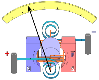
An ammeter is a measuring instrument used to measure the current in a circuit. Electric currents are measured in Amperes (A), hence the name. The ammeter is usually connected in series with the circuit in which the current is to be measured. An ammeter usually has low resistance so that it does not cause a significant voltage drop in the circuit being measured.

A resistor is a passive two-terminal electrical component that implements electrical resistance as a circuit element. In electronic circuits, resistors are used to reduce current flow, adjust signal levels, to divide voltages, bias active elements, and terminate transmission lines, among other uses. High-power resistors that can dissipate many watts of electrical power as heat may be used as part of motor controls, in power distribution systems, or as test loads for generators. Fixed resistors have resistances that only change slightly with temperature, time or operating voltage. Variable resistors can be used to adjust circuit elements, or as sensing devices for heat, light, humidity, force, or chemical activity.

A thermocouple is an electrical device consisting of two dissimilar electrical conductors forming an electrical junction. A thermocouple produces a temperature-dependent voltage as a result of the Seebeck effect, and this voltage can be interpreted to measure temperature. Thermocouples are widely used as temperature sensors.

An electrometer is an electrical instrument for measuring electric charge or electrical potential difference. There are many different types, ranging from historical handmade mechanical instruments to high-precision electronic devices. Modern electrometers based on vacuum tube or solid-state technology can be used to make voltage and charge measurements with very low leakage currents, down to 1 femtoampere. A simpler but related instrument, the electroscope, works on similar principles but only indicates the relative magnitudes of voltages or charges.
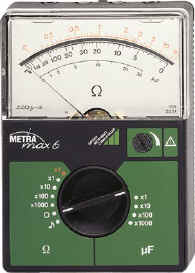
An ohmmeter is an electrical instrument that measures electrical resistance. Multimeters also function as ohmmeters when in resistance-measuring mode. An ohmmeter applies current to the circuit or component whose resistance is to be measured. It then measures the resulting voltage and calculates the resistance using Ohm’s law .

A multimeter is a measuring instrument that can measure multiple electrical properties. A typical multimeter can measure voltage, resistance, and current, in which case it is also known as a volt-ohm-milliammeter (VOM), as the unit is equipped with voltmeter, ammeter, and ohmmeter functionality. Some feature the measurement of additional properties such as temperature and capacitance.

In electrical engineering, ground or earth is a reference point in an electrical circuit from which voltages are measured, a common return path for electric current, or a direct physical connection to the Earth.

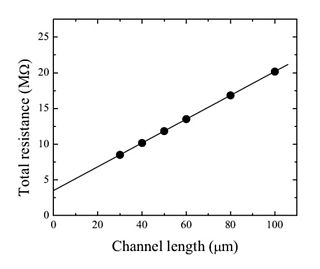
The electrical resistance of an object is a measure of its opposition to the flow of electric current. Its reciprocal quantity is electrical conductance, measuring the ease with which an electric current passes. Electrical resistance shares some conceptual parallels with mechanical friction. The SI unit of electrical resistance is the ohm, while electrical conductance is measured in siemens (S).

A short circuit is an electrical circuit that allows a current to travel along an unintended path with no or very low electrical impedance. This results in an excessive current flowing through the circuit. The opposite of a short circuit is an "open circuit", which is an infinite resistance between two nodes.
A strain gauge is a device used to measure strain on an object. Invented by Edward E. Simmons and Arthur C. Ruge in 1938, the most common type of strain gauge consists of an insulating flexible backing which supports a metallic foil pattern. The gauge is attached to the object by a suitable adhesive, such as cyanoacrylate. As the object is deformed, the foil is deformed, causing its electrical resistance to change. This resistance change, usually measured using a Wheatstone bridge, is related to the strain by the quantity known as the gauge factor.
Resistance thermometers, also called resistance temperature detectors (RTDs), are sensors used to measure temperature. Many RTD elements consist of a length of fine wire wrapped around a heat-resistant ceramic or glass core but other constructions are also used. The RTD wire is a pure material, typically platinum (Pt), nickel (Ni), or copper (Cu). The material has an accurate resistance/temperature relationship which is used to provide an indication of temperature. As RTD elements are fragile, they are often housed in protective probes.
A load cell is a force transducer. It converts a force such as tension, compression, pressure, or torque into an electrical signal that can be measured and standardized. As the force applied to the load cell increases, the electrical signal changes proportionally. The most common types of load cell used are strain gauges, pneumatic, and hydraulic.
In electronics, sense is a technique used in power supplies to produce the correct voltage for a load. Although simple batteries naturally maintain a steady voltage, a power supply must use a feedback system to make adjustments based on the difference between its intended output and its actual output. If this system is working, the latter will be very close to the former.
Voltage drop is the decrease of electrical potential along the path of a current flowing in an electrical circuit. Voltage drops in the internal resistance of the source, across conductors, across contacts, and across connectors are undesirable because some of the energy supplied is dissipated. The voltage drop across the electrical load is proportional to the power available to be converted in that load to some other useful form of energy.

A test probe is a physical device used to connect electronic test equipment to a device under test (DUT). Test probes range from very simple, robust devices to complex probes that are sophisticated, expensive, and fragile. Specific types include test prods, oscilloscope probes and current probes. A test probe is often supplied as a test lead, which includes the probe, cable and terminating connector.
The term contact resistance refers to the contribution to the total resistance of a system which can be attributed to the contacting interfaces of electrical leads and connections as opposed to the intrinsic resistance. This effect is described by the term electrical contact resistance (ECR) and arises as the result of the limited areas of true contact at an interface and the presence of resistive surface films or oxide layers. ECR may vary with time, most often decreasing, in a process known as resistance creep. The idea of potential drop on the injection electrode was introduced by William Shockley to explain the difference between the experimental results and the model of gradual channel approximation. In addition to the term ECR, interface resistance, transitional resistance, or just simply correction term are also used. The term parasitic resistance is used as a more general term, of which it is usually assumed that contact resistance is a major component.
A Kelvin bridge, also called a Kelvin double bridge and in some countries a Thomson bridge, is a measuring instrument used to measure unknown electrical resistors below 1 ohm. It is specifically designed to measure resistors that are constructed as four terminal resistors.
Soil resistivity is a measure of how much the soil resists or conducts electric current. It is a critical factor in design of systems that rely on passing current through the Earth's surface. It is a very important parameter for finding the best location of a transmitter working on low frequiencies as such radio stations usually use ground as counterpole. An understanding of the soil resistivity and how it varies with depth in the soil is necessary to design the grounding system in an electrical substation, or for lightning conductors. It is needed for design of grounding (earthing) electrodes for substations and High-voltage direct current transmission systems. It was formerly important in earth-return telegraphy. It can also be a useful measure in agriculture as a proxy measurement for moisture content.
In electrical engineering, current sensing is any one of several techniques used to measure electric current. The measurement of current ranges from picoamps to tens of thousands of amperes. The selection of a current sensing method depends on requirements such as magnitude, accuracy, bandwidth, robustness, cost, isolation or size. The current value may be directly displayed by an instrument, or converted to digital form for use by a monitoring or control system.

