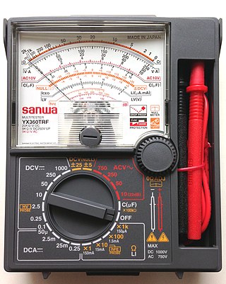
A multimeter is a measuring instrument that can measure multiple electrical properties. A typical multimeter can measure voltage, resistance, and current, in which case it is also known as a volt-ohm-milliammeter (VOM), as the unit is equipped with voltmeter, ammeter, and ohmmeter functionality, or volt-ohmmeter for short. Some feature the measurement of additional properties such as temperature and capacitance.

In electrical engineering, impedance is the opposition to alternating current presented by the combined effect of resistance and reactance in a circuit.
In electrical circuits, reactance is the opposition presented to alternating current by inductance or capacitance. Greater reactance gives smaller current for the same applied voltage. Reactance is similar to resistance in this respect, but does not lead to dissipation of electrical energy as heat; instead, energy is momentarily stored in the reactance, and a quarter-cycle later returned to the circuit.
Capacitance is the capability of a material object or device to store electric charge. It is measured by the change in charge in response to a difference in electric potential, expressed as the ratio of those quantities. Commonly recognized are two closely related notions of capacitance: self capacitance and mutual capacitance. An object that can be electrically charged exhibits self capacitance, for which the electric potential is measured between the object and ground. Mutual capacitance is measured between two components, and is particularly important in the operation of the capacitor, an elementary linear electronic component designed to add capacitance to an electric circuit.
In electrical engineering, electrical elements are conceptual abstractions representing idealized electrical components, such as resistors, capacitors, and inductors, used in the analysis of electrical networks. All electrical networks can be analyzed as multiple electrical elements interconnected by wires. Where the elements roughly correspond to real components, the representation can be in the form of a schematic diagram or circuit diagram. This is called a lumped-element circuit model. In other cases, infinitesimal elements are used to model the network, in a distributed-element model.

Electronic test equipment is used to create signals and capture responses from electronic devices under test (DUTs). In this way, the proper operation of the DUT can be proven or faults in the device can be traced. Use of electronic test equipment is essential to any serious work on electronics systems.

In electronics, a voltage divider (also known as a potential divider) is a passive linear circuit that produces an output voltage (Vout) that is a fraction of its input voltage (Vin). Voltage division is the result of distributing the input voltage among the components of the divider. A simple example of a voltage divider is two resistors connected in series, with the input voltage applied across the resistor pair and the output voltage emerging from the connection between them.
Practical capacitors and inductors as used in electric circuits are not ideal components with only capacitance or inductance. However, they can be treated, to a very good degree of approximation, as being ideal capacitors and inductors in series with a resistance; this resistance is defined as the equivalent series resistance (ESR). If not otherwise specified, the ESR is always an AC resistance, which means it is measured at specified frequencies, 100 kHz for switched-mode power supply components, 120 Hz for linear power-supply components, and at its self-resonant frequency for general-application components. Additionally, audio components may report a "Q factor", incorporating ESR among other things, at 1000 Hz.

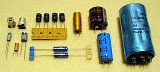
Capacitors are manufactured in many styles, forms, dimensions, and from a large variety of materials. They all contain at least two electrical conductors, called plates, separated by an insulating layer (dielectric). Capacitors are widely used as parts of electrical circuits in many common electrical devices.

A Q meter is a piece of equipment used in the testing of radio frequency circuits. It has been largely replaced in professional laboratories by other types of impedance measuring devices, though it is still in use among radio amateurs. It was developed at Boonton Radio Corporation in Boonton, New Jersey in 1934 by William D. Loughlin.

Electrical resonance occurs in an electric circuit at a particular resonant frequency when the impedances or admittances of circuit elements cancel each other. In some circuits, this happens when the impedance between the input and output of the circuit is almost zero and the transfer function is close to one.

A Maxwell bridge is a modification to a Wheatstone bridge used to measure an unknown inductance in terms of calibrated resistance and inductance or resistance and capacitance. When the calibrated components are a parallel resistor and capacitor, the bridge is known as a Maxwell bridge. It is named for James C. Maxwell, who first described it in 1873.

A capacitance meter is a piece of electronic test equipment used to measure capacitance, mainly of discrete capacitors. Depending on the sophistication of the meter, it may display the capacitance only, or it may also measure a number of other parameters such as leakage, equivalent series resistance (ESR), and inductance. For most purposes and in most cases the capacitor must be disconnected from circuit; ESR can usually be measured in circuit.

A test probe is a physical device used to connect electronic test equipment to a device under test (DUT). Test probes range from very simple, robust devices to complex probes that are sophisticated, expensive, and fragile. Specific types include test prods, oscilloscope probes and current probes. A test probe is often supplied as a test lead, which includes the probe, cable and terminating connector.
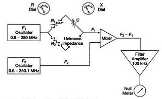
An RX meter is used to measure the separate resistive and reactive components of reactive parallel Z network.
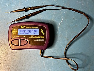
An ESR meter is a two-terminal electronic measuring instrument designed and used primarily to measure the equivalent series resistance (ESR) of real capacitors; usually without the need to disconnect the capacitor from the circuit it is connected to. Other types of meters used for routine servicing, including normal capacitance meters, cannot be used to measure a capacitor's ESR, although combined meters are available which measure both ESR and out-of-circuit capacitance. A standard (DC) milliohmmeter or multimeter cannot be used to measure ESR, because a steady direct current cannot be passed through the capacitor. Most ESR meters can also be used to measure non-inductive low-value resistances, whether or not associated with a capacitor; this leads to a number of additional applications described below.

Slotted lines are used for microwave measurements and consist of a movable probe inserted into a slot in a transmission line. They are used in conjunction with a microwave power source and usually, in keeping with their low-cost application, a low cost Schottky diode detector and VSWR meter rather than an expensive microwave power meter.
Aluminum electrolytic capacitors are polarized electrolytic capacitors whose anode electrode (+) is made of a pure aluminum foil with an etched surface. The aluminum forms a very thin insulating layer of aluminum oxide by anodization that acts as the dielectric of the capacitor. A non-solid electrolyte covers the rough surface of the oxide layer, serving in principle as the second electrode (cathode) (-) of the capacitor. A second aluminum foil called “cathode foil” contacts the electrolyte and serves as the electrical connection to the negative terminal of the capacitor.
An impedance analyzer is a type of electronic test equipment used to measure complex electrical impedance as a function of test frequency.
The transformer ratio arm bridge or TRA bridge is a type of bridge circuit used for measuring electronic components, using a.c. It can be designed to work in terms of either impedance or admittance. It can be used on resistors, capacitors and inductors, measuring minor as well as major terms, e.g. series resistance in capacitors. It is probably the most accurate type of bridge available, being capable of the precision needed, for example, when checking secondary component standards against national standards.


