Time-domain reflectometer

Last updated
Time-domain reflectometer for cable fault detection Megger Time-Domain Reflectometer MTDR1.jpg
Time-domain reflectometer for cable fault detection

A time-domain reflectometer (TDR) is an electronic instrument used to determine the characteristics of electrical lines by observing reflected pulses.

Contents

It can be used to characterize and locate faults in metallic cables (for example, twisted pair wire or coaxial cable), [1] and to locate discontinuities in a connector, printed circuit board, or any other electrical path.

Description

A TDR measures reflections along a conductor. In order to measure those reflections, the TDR will transmit an incident signal onto the conductor and listen for its reflections. If the conductor is of a uniform impedance and is properly terminated, then there will be no reflections and the remaining incident signal will be absorbed at the far-end by the termination. Instead, if there are impedance variations, then some of the incident signal will be reflected back to the source. A TDR is similar in principle to radar.

Signal (or energy) transmitted and reflected from a discontinuity Partial transmittance.gif
Signal (or energy) transmitted and reflected from a discontinuity

The impedance of the discontinuity can be determined from the amplitude of the reflected signal. The distance to the reflecting impedance can also be determined from the time that a pulse takes to return. The limitation of this method is the minimum system rise time. The total rise time consists of the combined rise time of the driving pulse and that of the oscilloscope or sampler that monitors the reflections.

Method

The TDR analysis begins with the propagation of a step or impulse of energy into a system and the subsequent observation of the energy reflected by the system. By analyzing the magnitude, duration and shape of the reflected waveform, the nature of the impedance variation in the transmission system can be determined.

If a pure resistive load is placed on the output of the reflectometer and a step signal is applied, a step signal is observed on the display, and its height is a function of the resistance. The magnitude of the step produced by the resistive load may be expressed as a fraction of the input signal as given by:

where is the characteristic impedance of the transmission line.

Reflection

Generally, the reflections will have the same shape as the incident signal, but their sign and magnitude depend on the change in impedance level. If there is a step increase in the impedance, then the reflection will have the same sign as the incident signal; if there is a step decrease in impedance, the reflection will have the opposite sign. The magnitude of the reflection depends not only on the amount of the impedance change, but also upon the loss in the conductor.

The reflections are measured at the output/input to the TDR and displayed or plotted as a function of time. Alternatively, the display can be read as a function of cable length because the speed of signal propagation is almost constant for a given transmission medium.

Because of its sensitivity to impedance variations, a TDR may be used to verify cable impedance characteristics, splice and connector locations and associated losses, and estimate cable lengths.

Incident signal

TDRs use different incident signals. Some TDRs transmit a pulse along the conductor; the resolution of such instruments is often the width of the pulse. Narrow pulses can offer good resolution, but they have high frequency signal components that are attenuated in long cables. The shape of the pulse is often a half cycle sinusoid. [2] For longer cables, wider pulse widths are used.

Fast rise time steps are also used. Instead of looking for the reflection of a complete pulse, the instrument is concerned with the rising edge, which can be very fast. [3] A 1970s technology TDR used steps with a rise time of 25 ps. [4] [5] [6]

Still other TDRs transmit complex signals and detect reflections with correlation techniques. See spread-spectrum time-domain reflectometry.

Variations and extensions

The equivalent device for optical fiber is an optical time-domain reflectometer.

Time-domain transmissometry (TDT) is an analogous technique that measures the transmitted (rather than reflected) impulse. Together, they provide a powerful means of analysing electrical or optical transmission media such as coaxial cable and optical fiber.

Variations of TDR exist. For example, spread-spectrum time-domain reflectometry (SSTDR) is used to detect intermittent faults in complex and high-noise systems such as aircraft wiring. [7] Coherent optical time domain reflectometry (COTDR) is another variant, used in optical systems, in which the returned signal is mixed with a local oscillator and then filtered to reduce noise. [8]

Example traces

These traces were produced by a time-domain reflectometer made from common lab equipment connected to approximately 100 feet (30 m) of coaxial cable having a characteristic impedance of 50 ohms. The propagation velocity of this cable is approximately 66% of the speed of light in a vacuum.

These traces were produced by a commercial TDR using a step waveform with a 25 ps risetime, a sampling head with a 35 ps risetime, and an 18-inch (0.46 m) SMA cable. [9] The far end of the SMA cable was left open or connected to different adapters. It takes about 3 ns for the pulse to travel down the cable, reflect, and reach the sampling head. A second reflection (at about 6 ns) can be seen in some traces; it is due to the reflection seeing a small mismatch at the sampling head and causing another "incident" wave to travel down the cable.

Explanation

If the far end of the cable is shorted, that is, terminated with an impedance of zero ohms, and when the rising edge of the pulse is launched down the cable, the voltage at the launching point "steps up" to a given value instantly and the pulse begins propagating in the cable towards the short. When the pulse encounters the short, no energy is absorbed at the far end. Instead, an inverted pulse reflects back from the short towards the launching end. It is only when this reflection finally reaches the launch point that the voltage at this point abruptly drops back to zero, signaling the presence of a short at the end of the cable. That is, the TDR has no indication that there is a short at the end of the cable until its emitted pulse can travel in the cable and the echo can return. It is only after this round-trip delay that the short can be detected by the TDR. With knowledge of the signal propagation speed in the particular cable-under-test, the distance to the short can be measured.

A similar effect occurs if the far end of the cable is an open circuit (terminated into an infinite impedance). In this case, though, the reflection from the far end is polarized identically with the original pulse and adds to it rather than cancelling it out. So after a round-trip delay, the voltage at the TDR abruptly jumps to twice the originally-applied voltage.

Perfect termination at the far end of the cable would entirely absorb the applied pulse without causing any reflection, rendering the determination of the actual length of the cable impossible. In practice, some small reflection is nearly always observed.

The magnitude of the reflection is referred to as the reflection coefficient or ρ. The coefficient ranges from 1 (open circuit) to −1 (short circuit). The value of zero means that there is no reflection. The reflection coefficient is calculated as follows:

Where Zo is defined as the characteristic impedance of the transmission medium and Zt is the impedance of the termination at the far end of the transmission line.

Any discontinuity can be viewed as a termination impedance and substituted as Zt. This includes abrupt changes in the characteristic impedance. As an example, a trace width on a printed circuit board doubled at its midsection would constitute a discontinuity. Some of the energy will be reflected back to the driving source; the remaining energy will be transmitted. This is also known as a scattering junction.

Usage

Time domain reflectometers are commonly used for in-place testing of very long cable runs, where it is impractical to dig up or remove what may be a kilometers-long cable. They are indispensable for preventive maintenance of telecommunication lines, as TDRs can detect resistance on joints and connectors as they corrode, and increasing insulation leakage as it degrades and absorbs moisture, long before either leads to catastrophic failures. Using a TDR, it is possible to pinpoint a fault to within centimetres.

TDRs are also very useful tools for technical surveillance counter-measures, where they help determine the existence and location of wire taps. The slight change in line impedance caused by the introduction of a tap or splice will show up on the screen of a TDR when connected to a phone line.

TDR equipment is also an essential tool in the failure analysis of modern high-frequency printed circuit boards with signal traces crafted to emulate transmission lines. By observing reflections, any unsoldered pins of a ball grid array device can be detected. Short circuited pins can also be detected in a similar fashion.

The TDR principle is used in industrial settings, in situations as diverse as the testing of integrated circuit packages to measuring liquid levels. In the former, the time domain reflectometer is used to isolate failing sites in the same. The latter is primarily limited to the process industry.

In level measurement

In a TDR-based level measurement device, the device generates an impulse that propagates down a thin waveguide (referred to as a probe) – typically a metal rod or a steel cable. When this impulse hits the surface of the medium to be measured, part of the impulse reflects back up the waveguide. The device determines the fluid level by measuring the time difference between when the impulse was sent and when the reflection returned. The sensors can output the analyzed level as a continuous analog signal or switch output signals. In TDR technology, the impulse velocity is primarily affected by the permittivity of the medium through which the pulse propagates, which can vary greatly by the moisture content and temperature of the medium. In many cases, this effect can be corrected without undue difficulty. In some cases, such as in boiling and/or high temperature environments, the correction can be difficult. In particular, determining the froth (foam) height and the collapsed liquid level in a frothy / boiling medium can be very difficult.

Used in anchor cables in dams

The Dam Safety Interest Group of CEA Technologies, Inc. (CEATI), a consortium of electrical power organizations, has applied Spread-spectrum time-domain reflectometry to identify potential faults in concrete dam anchor cables. The key benefit of Time Domain reflectometry over other testing methods is the non-destructive method of these tests. [10]

Used in the earth and agricultural sciences

A TDR is used to determine moisture content in soil and porous media. Over the last two decades, substantial advances have been made measuring moisture in soil, grain, food stuff, and sediment. The key to TDR's success is its ability to accurately determine the permittivity (dielectric constant) of a material from wave propagation, due to the strong relationship between the permittivity of a material and its water content, as demonstrated in the pioneering works of Hoekstra and Delaney (1974) and Topp et al. (1980). Recent reviews and reference work on the subject include, Topp and Reynolds (1998), Noborio (2001), Pettinellia et al. (2002), Topp and Ferre (2002) and Robinson et al. (2003). The TDR method is a transmission line technique, and determines apparent permittivity (Ka) from the travel time of an electromagnetic wave that propagates along a transmission line, usually two or more parallel metal rods embedded in soil or sediment. The probes are typically between 10 and 30 cm long and connected to the TDR via coaxial cable.

In geotechnical engineering

Time domain reflectometry has also been utilized to monitor slope movement in a variety of geotechnical settings including highway cuts, rail beds, and open pit mines (Dowding & O'Connor, 1984, 2000a, 2000b; Kane & Beck, 1999). In stability monitoring applications using TDR, a coaxial cable is installed in a vertical borehole passing through the region of concern. The electrical impedance at any point along a coaxial cable changes with deformation of the insulator between the conductors. A brittle grout surrounds the cable to translate earth movement into an abrupt cable deformation that shows up as a detectable peak in the reflectance trace. Until recently, the technique was relatively insensitive to small slope movements and could not be automated because it relied on human detection of changes in the reflectance trace over time. Farrington and Sargand (2004) developed a simple signal processing technique using numerical derivatives to extract reliable indications of slope movement from the TDR data much earlier than by conventional interpretation.

Another application of TDRs in geotechnical engineering is to determine the soil moisture content. This can be done by placing the TDRs in different soil layers and measurement of the time of start of precipitation and the time that TDR indicate an increase in the soil moisture content. The depth of the TDR (d) is a known factor and the other is the time it takes the drop of water to reach that depth (t); therefore the speed of water infiltration (v) can be determined. This is a good method to assess the effectiveness of Best Management Practices (BMPs) in reducing stormwater surface runoff.

In semiconductor device analysis

Time domain reflectometry is used in semiconductor failure analysis as a non-destructive method for the location of defects in semiconductor device packages. The TDR provides an electrical signature of individual conductive traces in the device package, and is useful for determining the location of opens and shorts.

In aviation wiring maintenance

Time domain reflectometry, specifically spread-spectrum time-domain reflectometry is used on aviation wiring for both preventive maintenance and fault location. [11] Spread spectrum time domain reflectometry has the advantage of precisely locating the fault location within thousands of miles of aviation wiring. Additionally, this technology is worth considering for real time aviation monitoring, as spread spectrum reflectometry can be employed on live wires.

This method has been shown to be useful to locating intermittent electrical faults. [12]

Multi carrier time domain reflectometry (MCTDR) has also been identified as a promising method for embedded EWIS diagnosis or troubleshooting tools. Based on the injection of a multicarrier signal (respecting EMC and harmless for the wires), this smart technology provides information for the detection, localization and characterization of electrical defects (or mechanical defects having electrical consequences) in the wiring systems. Hard fault (short, open circuit) or intermittent defects can be detected very quickly increasing the reliability of wiring systems and improving their maintenance. [13]

See also

Related Research Articles

<span class="mw-page-title-main">Optical time-domain reflectometer</span> Optoelectronic instrument

An optical time-domain reflectometer (OTDR) is an optoelectronic instrument used to characterize an optical fiber. It is the optical equivalent of an electronic time domain reflectometer which measures the impedance of the cable or transmission line under test. An OTDR injects a series of optical pulses into the fiber under test and extracts, from the same end of the fiber, light that is scattered or reflected back from points along the fiber. The scattered or reflected light that is gathered back is used to characterize the optical fiber. The strength of the return pulses is measured and integrated as a function of time, and plotted as a function of length of the fiber.

<span class="mw-page-title-main">Standing wave ratio</span> Measure used in radio engineering and telecommunications

In radio engineering and telecommunications, standing wave ratio (SWR) is a measure of impedance matching of loads to the characteristic impedance of a transmission line or waveguide. Impedance mismatches result in standing waves along the transmission line, and SWR is defined as the ratio of the partial standing wave's amplitude at an antinode (maximum) to the amplitude at a node (minimum) along the line.

<span class="mw-page-title-main">Transmission line</span> Cable or other structure for carrying radio waves

In electrical engineering, a transmission line is a specialized cable or other structure designed to conduct electromagnetic waves in a contained manner. The term applies when the conductors are long enough that the wave nature of the transmission must be taken into account. This applies especially to radio-frequency engineering because the short wavelengths mean that wave phenomena arise over very short distances. However, the theory of transmission lines was historically developed to explain phenomena on very long telegraph lines, especially submarine telegraph cables.

<span class="mw-page-title-main">Signal reflection</span> When a transmitted signal reflects back through the medium it was transmitted over

In telecommunications, signal reflection occurs when a signal is transmitted along a transmission medium, such as a copper cable or an optical fiber. Some of the signal power may be reflected back to its origin rather than being carried all the way along the cable to the far end. This happens because imperfections in the cable cause impedance mismatches and non-linear changes in the cable characteristics. These abrupt changes in characteristics cause some of the transmitted signal to be reflected. In radio frequency (RF) practice this is often measured in a dimensionless ratio known as voltage standing wave ratio (VSWR) with a VSWR bridge. The ratio of energy bounced back depends on the impedance mismatch. Mathematically, it is defined using the reflection coefficient.

This is an index of articles relating to electronics and electricity or natural electricity and things that run on electricity and things that use or conduct electricity.

In electrical engineering, partial discharge (PD) is a localized dielectric breakdown (DB) of a small portion of a solid or fluid electrical insulation (EI) system under high voltage (HV) stress. While a corona discharge (CD) is usually revealed by a relatively steady glow or brush discharge (BD) in air, partial discharges within solid insulation system are not visible.

Frequency domain (FD) sensor is an instrument developed for measuring soil moisture content. The instrument has an oscillating circuit, the sensing part of the sensor is embedded in the soil, and the operating frequency will depend on the value of soil's dielectric constant.

In an electric power system, a fault or fault current is any abnormal electric current. For example, a short circuit is a fault in which a live wire touches a neutral or ground wire. An open-circuit fault occurs if a circuit is interrupted by a failure of a current-carrying wire or a blown fuse or circuit breaker. In three-phase systems, a fault may involve one or more phases and ground, or may occur only between phases. In a "ground fault" or "earth fault", current flows into the earth. The prospective short-circuit current of a predictable fault can be calculated for most situations. In power systems, protective devices can detect fault conditions and operate circuit breakers and other devices to limit the loss of service due to a failure.

Distributed temperature sensing systems (DTS) are optoelectronic devices which measure temperatures by means of optical fibres functioning as linear sensors. Temperatures are recorded along the optical sensor cable, thus not at points, but as a continuous profile. A high accuracy of temperature determination is achieved over great distances. Typically the DTS systems can locate the temperature to a spatial resolution of 1 m with accuracy to within ±1 °C at a resolution of 0.01 °C. Measurement distances of greater than 30 km can be monitored and some specialised systems can provide even tighter spatial resolutions. Thermal changes along the optical fibre cause a local variation in the refractive index, which in turn leads to the inelastic scattering of the light propagating through it. Heat is held in the form of molecular or lattice vibrations in the material. Molecular vibrations at high frequencies (10 THz) are responsible for Raman scattering. Low frequency vibrations (10–30 GHz) cause Brillouin scattering. Energy is exchanged between the light travelling through the fibre and the material itself and cause a frequency shift in the incident light. This frequency shift can then be used to measure temperature changes along the fibre.

<span class="mw-page-title-main">Oscilloscope</span> Instrument for displaying time-varying signals

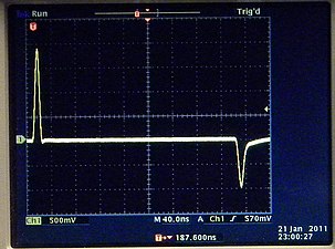
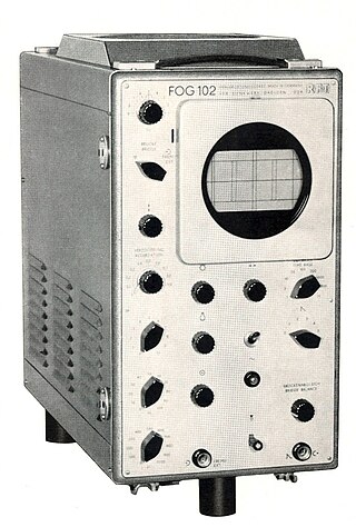
An oscilloscope is a type of electronic test instrument that graphically displays varying voltages of one or more signals as a function of time. Their main purpose is capturing information on electrical signals for debugging, analysis, or characterization. The displayed waveform can then be analyzed for properties such as amplitude, frequency, rise time, time interval, distortion, and others. Originally, calculation of these values required manually measuring the waveform against the scales built into the screen of the instrument. Modern digital instruments may calculate and display these properties directly.

Transmission-Line Pulse (TLP) is a way to study integrated circuit technologies and circuit behavior in the current and time domain of electrostatic-discharge (ESD) events. The concept was described shortly after WWII in pp. 175–189 of Pulse Generators, Vol. 5 of the MIT Radiation Lab Series. Also, D. Bradley, J. Higgins, M. Key, and S. Majumdar realized a TLP-based laser-triggered spark gap for kilovolt pulses of accurately variable timing in 1969. For investigation of ESD and electrical-overstress (EOS) effects a measurement system using a TLP generator has been introduced first by T. Maloney and N. Khurana in 1985. Since then, the technique has become indispensable for integrated circuit ESD protection development.

<span class="mw-page-title-main">Soil moisture sensor</span> Instrument to measure soil water content

Soil moisture sensors measure the volumetric water content in soil. Since the direct gravimetric measurement of free soil moisture requires removing, drying, and weighing of a sample, soil moisture sensors measure the volumetric water content indirectly by using some other property of the soil, such as electrical resistance, dielectric constant, or interaction with neutrons, as a proxy for the moisture content.

<span class="mw-page-title-main">Reflections of signals on conducting lines</span> Electrical waves in return direction

A signal travelling along an electrical transmission line will be partly, or wholly, reflected back in the opposite direction when the travelling signal encounters a discontinuity in the characteristic impedance of the line, or if the far end of the line is not terminated in its characteristic impedance. This can happen, for instance, if two lengths of dissimilar transmission lines are joined.

Spread-spectrum time-domain reflectometry (SSTDR) is a measurement technique to identify faults, usually in electrical wires, by observing reflected spread spectrum signals. This type of time-domain reflectometry can be used in various high-noise and live environments. Additionally, SSTDR systems have the additional benefit of being able to precisely locate the position of the fault. Specifically, SSTDR is accurate to within a few centimeters for wires carrying 400 Hz aircraft signals as well as MIL-STD-1553 data bus signals. AN SSTDR system can be run on a live wire because the spread spectrum signals can be isolated from the system noise and activity.

Noise-domain reflectometry is a type of reflectometry where the reflectometer exploits existing data signals on wiring and does not have to generate any signals itself. Noise-domain reflectometry, like time-domain and spread-spectrum time domain reflectometers, is most often used in identifying the location of wire faults in electrical lines.

An arc fault is a high power discharge of electricity between two or more conductors. This discharge generates heat, which can break down the wire's insulation and trigger an electrical fire. Arc faults can range in current from a few amps up to thousands of amps, and are highly variable in strength and duration.

Rayleigh scattering based distributed acoustic sensing (DAS) systems use fiber optic cables to provide distributed strain sensing. In DAS, the optical fiber cable becomes the sensing element and measurements are made, and in part processed, using an attached optoelectronic device. Such a system allows acoustic frequency strain signals to be detected over large distances and in harsh environments.

<span class="mw-page-title-main">Cable fault location</span> Process of locating electrical faults in cables

Cable fault location is the process of locating periodic faults, such as insulation faults in cables. In this process, mobile shock discharge generators are among the devices used.

Reflectometry is a general term for the use of the reflection of waves or pulses at surfaces and interfaces to detect or characterize objects, sometimes to detect anomalies as in fault detection and medical diagnosis.

<span class="mw-page-title-main">TDR moisture sensor</span>

A TDR moisture sensor employs time-domain reflectometry (TDR) to measure moisture content indirectly based on the correlation to electric and dielectric properties of materials, such as soil, agrarian products, snow, wood or concrete.

References

  1. PD-icon.svg This article incorporates public domain material from Federal Standard 1037C. General Services Administration. Archived from the original on 2022-01-22.
  2. 1983 Tektronix Catalog, pages 140–141, the 1503 uses "1/2-sine-shaped pulses" and has a 3-foot resolution and a range of 50,000 feet.
  3. 1983 Tektronix Catalog, pages 140–141, the 1502 uses a step (system rise time less than 140 ps), has a resolution of 0.6 inch and a range of 2,000 feet.
  4. 1983 Tektronix Catalog, page 289, S-52 pulse generator has a 25-ps risetime.
  5. S-6 Sampling Head, Instruction Manual, Beaverton, OR: Tektronix, September 1982 First printing is 1982, but copyright notice includes 1971.
  6. 7S12 TDR/Sampler, Instruction Manual, Beaverton, OR: Tektronix, November 1971
  7. Smith, Paul, Furse, Cynthia and Gunther, Jacob. "Analysis of Spread Spectrum Time Domain Reflectometry for Wire Fault Location Archived 2010-12-31 at the Wayback Machine ." IEEE Sensors Journal. December, 2005.
  8. José Chesnoy (ed.), Undersea Fiber Communication Systems, Elsevier Science, 2002, ISBN   0-12-171408-X, p.171 (COTDR)
  9. Hamilton Avnet part number P-3636-603-5215
  10. C. Furse, P. Smith, M. Diamond, "Feasibility of Reflectometry for Nondestructive Evaluation of Prestressed Concrete Anchors," IEEE Journal of Sensors, Vol. 9. No. 11, Nov. 2009, pp. 1322–1329
  11. Smith, P., C. Furse, and J. Gunther, 2005. "Analysis of spread spectrum time domain reflectometry for wire fault location Archived 2010-12-31 at the Wayback Machine ". IEEE Sensors Journal 5:1469–1478.
  12. Furse, Cynthia, Smith, P., Safavi, Mehdi, and M. Lo, Chet. "Feasibility of Spread Spectrum Sensors for Location of Arcs on Live Wires Archived 2010-05-01 at archive.today ". IEEE Sensors Journal. December 2005.
  13. G.Millet, S.Bruillot, D.Dejardin, N.Imbert, F.Auzanneau, L.Incarbone, M.Olivas, L.Vincent, A.Cremzi, S.Poignant, 2014."Aircraft Electrical Wiring Monitoring System"

Further reading