Hydrogen-cooled turbo generator

Last updated
A power plant turbine generator set: A steam turbine (blue) drives an electrical generator (yellow) with an excitation generator (front). Turbinenhalle KSP.jpg
A power plant turbine generator set: A steam turbine (blue) drives an electrical generator (yellow) with an excitation generator (front).
A 500 MW Siemens multi stage steam turbine with generator set (rear, red) Turbogenerator01.jpg
A 500 MW Siemens multi stage steam turbine with generator set (rear, red)

A hydrogen-cooled turbo generator is a turbo generator with gaseous hydrogen as a coolant. Hydrogen-cooled turbo generators are designed to provide a low-drag atmosphere and cooling for single-shaft and combined-cycle applications in combination with steam turbines. [1] Because of the high thermal conductivity and other favorable properties of hydrogen gas, this is the most common type in its field today.

Contents

History

Based on the air-cooled turbo generator, gaseous hydrogen first went into service as the coolant in a hydrogen-cooled turbo generator in October 1937, at the Dayton Power & Light Co. in Dayton, Ohio. [2]

Design

The use of gaseous hydrogen as a coolant is based on its properties, namely low density, high specific heat, and the highest thermal conductivity (at 0.168 W/(m·K)) of all gases; it is 7 to 10 times better at cooling than air. [3] Another advantage of hydrogen is its easy detection by hydrogen sensors. A hydrogen-cooled generator can be significantly smaller, and therefore less expensive, than an air-cooled one. For stator cooling, water can be used.

Helium with a thermal-conductivity of 0.142 W/(m·K) was considered as coolant as well; however, its high cost hinders its adoption despite its non-flammability. [4]

Generally, three cooling approaches are used. For generators up to 60 MW, air cooling can be used. Between 60 and 450 MW hydrogen cooling is employed. For the highest power generators, up to 1800 MW, hydrogen and water cooling is used; the rotor is hydrogen-cooled, while the stator windings are made of hollow copper tubes cooled by water circulating through them.

The generators produce high voltage; the choice of voltage depends on the tradeoff between demands of electrical insulation and handling high electric current. For generators up to 40 MVA, the voltage is 6.3 kV; large generators with power above 1000 MW generate voltages up to 27 kV; voltages between 2.3 and 30 kV are used depending on the size of the generator. The generated power is sent to a nearby step-up transformer, where it is converted to the electric power transmission line voltage (typically between 115 and 1200 kV).

To control the centrifugal forces at high rotational speeds, the rotor diameter typically does not exceed 1.25 meters; the required large size of the coils is achieved by their length and so the generator is mounted horizontally. Two-pole machines typically operate at 3000 rpm for 50 Hz and 3600 rpm for 60 Hz systems, half of that for four-pole machines.

The turbogenerator also contains a smaller generator producing direct current excitation power for the rotor coil. Older generators used dynamos and slip rings for DC injection to the rotor, but the moving mechanical contacts were subject to wear. Modern generators have the excitation generator on the same shaft as the turbine and main generator; the diodes needed are located directly on the rotor. The excitation current on larger generators can reach 10 kA. The amount of excitation power ranges between 0.5 and 3% of the generator output power.

The rotor usually contains caps or cage made of nonmagnetic material; its role is to provide a low impedance path for eddy currents which occur when the three phases of the generator are unevenly loaded. In such cases, eddy currents are generated in the rotor, and the resulting Joule heating could in extreme cases destroy the generator. [5]

Hydrogen gas is circulated in a closed loop to remove heat from the active parts then it is cooled by gas-to-water heat exchangers on the stator frame. The working pressure is up to 6  bar.

An on-line thermal conductivity detector (TCD) analyzer is used with three measuring ranges. The first range (80–100% H2) is to monitor the hydrogen purity during normal operation. The second (0–100% H2) and third (0–100% CO2) measuring ranges allow safe opening of the turbines for maintenance. [6]

Hydrogen has very low viscosity, a favorable property for reducing drag losses in the rotor. These losses can be significant due to the rotor's high rotational speed. A reduction in the purity of the hydrogen coolant increases windage losses in the turbine due to the associated increase in viscosity and drag. A drop in hydrogen purity from 98% to 95% in a large generator can increase windage losses by 32%; this is equivalent to 685 KW for a 907 MW generator. [7] Windage losses also increase heat loss in the generator and increase the problem of dealing with the waste heat. [8]

Operation

The absence of oxygen in the atmosphere within significantly reduces damage to the winding insulation from corona discharges; these can be problematic as the generators typically operate at high voltage, often 20 kV. [9]

Seal oil system

The bearings have to be leak-tight. A hermetic seal, usually a liquid seal, is employed; a turbine oil at pressure higher than the hydrogen inside is typically used. A metal, e.g. brass, ring is pressed by springs onto the generator shaft, the oil is forced under pressure between the ring and the shaft; part of the oil flows into the hydrogen side of the generator, another part to the air side. The oil entrains a small amount of air; as the oil is recirculated, some of the air is carried over into the generator. This causes a gradual air contamination buildup and requires maintaining hydrogen purity. [10]

Scavenging systems are used for this purpose; gas (mixture of entrained air and hydrogen, released from the oil) is collected in the holding tank for the sealing oil, and released into the atmosphere; the hydrogen losses have to be replenished, either from gas cylinders or from on-site hydrogen generators. Degradation of bearings leads to higher oil leaks, which increases the amount of air transferred into the generator. Increased oil consumption can be detected by a flow meter for each bearing. [10]

Drying

Presence of water in hydrogen has to be avoided, as it causes deterioration of hydrogen's cooling properties, corrosion of the generator parts, and arcing in the high voltage windings, and reduces the lifetime of the generator. A desiccant-based dryer is usually included in the gas circulation loop, typically with a moisture probe in the dryer's outlet, sometimes also in its inlet. Presence of moisture is also indirect evidence of air leaking into the generator compartment. [7] Another option is optimizing the hydrogen scavenging, so the dew point is kept within the generator's specifications. The water is usually introduced into the generator atmosphere as an impurity in the turbine oil; another route is via leaks in water cooling systems. [11]

Purging

The flammability limits (4–75% of hydrogen in air at normal temperature, wider at high temperatures, [12] ), its autoignition temperature at 571 °C, its very low minimum ignition energy, and its tendency to form explosive mixtures with air, require provisions to be made for maintaining the hydrogen content within the generator above the upper or below the lower flammability limit at all times, and other hydrogen safety measures. When the generator is filled with hydrogen, overpressure has to be maintained as inflow of air into the generator could cause a dangerous explosion in its confined space.

The generator enclosure is purged before opening it for maintenance, and before refilling the generator with hydrogen. During shutdown, hydrogen is purged by an inert gas, and then the inert gas is replaced by air; the opposite sequence is used before startup. Carbon dioxide or nitrogen can be used for this purpose, as they do not form combustible mixtures with hydrogen and are inexpensive. Gas purity sensors are used to indicate the end of the purging cycle, which shortens the startup and shutdown times and reduces consumption of the purging gas.

Carbon dioxide is favored as due to the very high density difference it easily displaces the hydrogen. The carbon dioxide is admitted to the bottom of the generator first, pushing the hydrogen out at the top. Then air is admitted to the top, pushing the carbon dioxide out at the bottom. Purging is best done with the generator stopped. If it is done during slow-speed unloaded rotation, the generator fans will mix the gases, greatly increasing the time required to achieve purity.

Make-up

Hydrogen is often produced on-site using a plant consisting of an array of electrolysis cells, compressors and storage vessels. This reduces the need for storing compressed hydrogen and allows storage in lower pressure tanks, with associated safety benefits and lower costs. Some gaseous hydrogen has to be kept for refilling the generator but it can be also generated on-site.

As technology evolves materials not susceptible to hydrogen embrittlement are used in generator designs. Not doing so can lead to equipment failure from hydrogen embrittlement. [13]

See also

Related Research Articles

<span class="mw-page-title-main">Turbine</span> Rotary mechanical device that extracts energy from a fluid flow

A turbine is a rotary mechanical device that extracts energy from a fluid flow and converts it into useful work. The work produced can be used for generating electrical power when combined with a generator. A turbine is a turbomachine with at least one moving part called a rotor assembly, which is a shaft or drum with blades attached. Moving fluid acts on the blades so that they move and impart rotational energy to the rotor. Early turbine examples are windmills and waterwheels.

<span class="mw-page-title-main">Gas turbine</span> Type of internal and continuous combustion engine

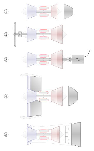
A gas turbine or gas turbine engine, by its old name internal combustion turbine, is a type of continuous flow internal combustion engine. The main parts common to all gas turbine engines form the power-producing part and are, in the direction of flow:

<span class="mw-page-title-main">Electric generator</span> Device that converts other energy to electrical energy

In electricity generation, a generator is a device that converts motion-based power or fuel-based power into electric power for use in an external circuit. Sources of mechanical energy include steam turbines, gas turbines, water turbines, internal combustion engines, wind turbines and even hand cranks. The first electromagnetic generator, the Faraday disk, was invented in 1831 by British scientist Michael Faraday. Generators provide nearly all the power for electrical grids.

<span class="mw-page-title-main">Power station</span> Facility generating electric power

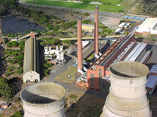
A power station, also referred to as a power plant and sometimes generating station or generating plant, is an industrial facility for the generation of electric power. Power stations are generally connected to an electrical grid.

<span class="mw-page-title-main">Combined cycle power plant</span> Assembly of heat engines that work in tandem from the same source of heat

A combined cycle power plant is an assembly of heat engines that work in tandem from the same source of heat, converting it into mechanical energy. On land, when used to make electricity the most common type is called a combined cycle gas turbine (CCGT) plant. The same principle is also used for marine propulsion, where it is called a combined gas and steam (COGAS) plant. Combining two or more thermodynamic cycles improves overall efficiency, which reduces fuel costs.

Internal combustion engine cooling uses either air or liquid to remove the waste heat from an internal combustion engine. For small or special purpose engines, cooling using air from the atmosphere makes for a lightweight and relatively simple system. Watercraft can use water directly from the surrounding environment to cool their engines. For water-cooled engines on aircraft and surface vehicles, waste heat is transferred from a closed loop of water pumped through the engine to the surrounding atmosphere by a radiator.

<span class="mw-page-title-main">Cogeneration</span> Simultaneous generation of electricity and useful heat

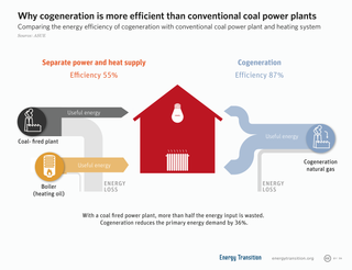
Cogeneration or combined heat and power (CHP) is the use of a heat engine or power station to generate electricity and useful heat at the same time.

A coolant is a substance, typically liquid, that is used to reduce or regulate the temperature of a system. An ideal coolant has high thermal capacity, low viscosity, is low-cost, non-toxic, chemically inert and neither causes nor promotes corrosion of the cooling system. Some applications also require the coolant to be an electrical insulator.

<span class="mw-page-title-main">Thermal power station</span> Power plant that generates electricity from heat energy

A thermal power station is a type of power station in which heat energy is converted to electrical energy. In a steam-generating cycle heat is used to boil water in a large pressure vessel to produce high-pressure steam, which drives a steam turbine connected to an electrical generator. The low-pressure exhaust from the turbine enters a steam condenser where it is cooled to produce hot condensate which is recycled to the heating process to generate more high pressure steam. This is known as a Rankine cycle.

<span class="mw-page-title-main">Turbo generator</span>

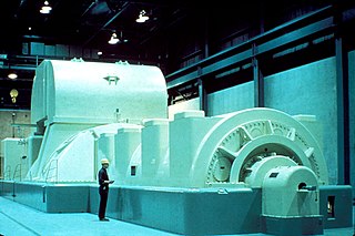
A turbo generator is an electric generator connected to the shaft of a steam turbine or gas turbine for the generation of electric power. Large steam-powered turbo generators provide the majority of the world's electricity and are also used by steam-powered turbo-electric ships.

<span class="mw-page-title-main">Absorption refrigerator</span> Refrigerator that uses a heat source

An absorption refrigerator is a refrigerator that uses a heat source to provide the energy needed to drive the cooling process. Solar energy, burning a fossil fuel, waste heat from factories, and district heating systems are examples of convenient heat sources that can be used. An absorption refrigerator uses two coolants: the first coolant performs evaporative cooling and then is absorbed into the second coolant; heat is needed to reset the two coolants to their initial states. Absorption refrigerators are commonly used in recreational vehicles (RVs), campers, and caravans because the heat required to power them can be provided by a propane fuel burner, by a low-voltage DC electric heater or by a mains-powered electric heater. Absorption refrigerators can also be used to air-condition buildings using the waste heat from a gas turbine or water heater in the building. Using waste heat from a gas turbine makes the turbine very efficient because it first produces electricity, then hot water, and finally, air-conditioning—trigeneration.

<span class="mw-page-title-main">Turboexpander</span>

A turboexpander, also referred to as a turbo-expander or an expansion turbine, is a centrifugal or axial-flow turbine, through which a high-pressure gas is expanded to produce work that is often used to drive a compressor or generator.

<span class="mw-page-title-main">Damhead Creek power station</span> Gas-fired power station in Kent, England

Damhead Creek power station is a 792 MWe gas-fired power station in Kent, England, on the Hoo Peninsula, It is near the site of the decommissioned Kingsnorth power station. The plant entered service in February 2001.

<span class="mw-page-title-main">South Humber Bank Power Station</span> Gas-fired power station

South Humber Bank Power Station is a 1,365 MW gas-fired power station on South Marsh Road at Stallingborough in North East Lincolnshire north of Healing and the A180 near the South Marsh Road Industrial Estate. It is around two miles east of Immingham, and employs 64 people. The site of SHBPS is around 500 metres by 400 metres in area. It is next door to the Synthomer plant.

<span class="mw-page-title-main">West Burton power stations</span> Coal and gas fired power stations in Nottinghamshire, England

The West Burton power stations are a pair of power stations on the River Trent near Gainsborough, Lincolnshire, England. West Burton A was a coal-fired power station, which was commissioned in 1966 and operated until 2023, and West Burton B is a combined cycle gas turbine power station, commissioned in 2013. West Burton A is owned by EDF Energy, while West Burton B is owned and operated by EIG Global Energy Partners.

The three primary objectives of nuclear reactor safety systems as defined by the U.S. Nuclear Regulatory Commission are to shut down the reactor, maintain it in a shutdown condition and prevent the release of radioactive material.

<span class="mw-page-title-main">Copper in renewable energy</span> The use of copper in renewable energy

Renewable energy sources such as solar, wind, tidal, hydro, biomass, and geothermal have become significant sectors of the energy market. The rapid growth of these sources in the 21st century has been prompted by increasing costs of fossil fuels as well as their environmental impact issues that significantly lowered their use.

<span class="mw-page-title-main">Internal combustion engine</span> Engine in which the combustion of a fuel occurs with an oxidizer in a combustion chamber

An internal combustion engine is a heat engine in which the combustion of a fuel occurs with an oxidizer in a combustion chamber that is an integral part of the working fluid flow circuit. In an internal combustion engine, the expansion of the high-temperature and high-pressure gases produced by combustion applies direct force to some component of the engine. The force is typically applied to pistons, turbine blades, a rotor, or a nozzle. This force moves the component over a distance, transforming chemical energy into kinetic energy which is used to propel, move or power whatever the engine is attached to.

<span class="mw-page-title-main">Hrazdan Thermal Power Plant</span>

Hrazdan Thermal Power Plant is a natural gas-fired power plant in the northwestern part of Hrazdan city, generating electricity in Armenia. It is one of the largest power plants in Armenia. This power plant was built in 1963–1974, and the first unit became operational in 1966. In 2013, a new unit was added. Four older units of the plant are owned and operated by the Hrazdan Power Company, a subsidiary of Tashir Capital owned by the family of Samvel Karapetyan. The new fifth unit is owned and operated by Gazprom Armenia.

<span class="mw-page-title-main">Organic nuclear reactor</span> Nuclear reactor that uses organic liquids for cooling and neutron moderation

An organic nuclear reactor, or organic cooled reactor (OCR), is a type of nuclear reactor that uses some form of organic fluid, typically a hydrocarbon substance like polychlorinated biphenyl (PCB), for cooling and sometimes as a neutron moderator as well.

References

  1. Nagano, S.; Kitajima, T.; Yoshida, K.; Kazao, Y.; Kabata, Y.; Murata, D.; Nagakura, K. (1 July 2002). "Development of world's largest hydrogen-cooled turbine generator". IEEE Power Engineering Society Summer Meeting. Vol. 2. pp. 657–663 vol.2. doi:10.1109/PESS.2002.1043376. ISBN   978-0-7803-7518-5. S2CID   37954073 via IEEE Xplore.
  2. "Full text of "A chronological history of electrical development from 600 B.C."". archive.org. 1946.
  3. "Hydrogen Cools Well, but Safety is Crucial". Power Engineering . Retrieved 8 October 2017. hydrogen's low density, high specific heat and thermal conductivity make it a superior coolant for this application ... Hydrogen has one of the best heat transfer properties of any gas, with a specific heat of 3.4 Btu/lb-F at standard conditions. On a mass basis, hydrogen is 14 times more efficient than dry air for removing heat ... Hydrogen, as the lightest gas, has the lowest density of any stable gas. Wind resistance losses are kept to a minimum because the rotor's wind resistance in a hydrogen-cooled generator is far less than in a similarly sized air-cooled generator
  4. [ permanent dead link ]
  5. "Damper winding for turbine generator rotors". www.freepatentsonline.com.
  6. "Gas Analyzer constantly monitors hydrogen purity". news.thomasnet.com.
  7. 1 2 "Hydrogen Purity in Hydrogen-Cooled Generators" (PDF). www.gesensing.com. Archived from the original (PDF) on 2008-11-16.
  8. [ permanent dead link ]
  9. "Gas Turbines". GE Power Generation. Archived from the original on 2010-05-05. Retrieved 2010-03-10.
  10. 1 2 "Generator Hydrogen Cooling System". www.control.com.
  11. "Water Contamination in Hydrogen-Cooled Generators Lurks as Serious Operational Threat". www.powergenworldwide.com.
  12. "Module 1: Hydrogen Properties" (PDF).
  13. "Lessons Learned - Hydrogen Tools". h2incidents.org.