
A cam is a rotating or sliding piece in a mechanical linkage used especially in transforming rotary motion into linear motion. It is often a part of a rotating wheel or shaft that strikes a lever at one or more points on its circular path. The cam can be a simple tooth, as is used to deliver pulses of power to a steam hammer, for example, or an eccentric disc or other shape that produces a smooth reciprocating motion in the follower, which is a lever making contact with the cam. A cam timer is similar, and were widely used for electric machine control before the advent of inexpensive electronics, microcontrollers, integrated circuits, programmable logic controllers and digital control.
A machine is a physical system using power to apply forces and control movement to perform an action. The term is commonly applied to artificial devices, such as those employing engines or motors, but also to natural biological macromolecules, such as molecular machines. Machines can be driven by animals and people, by natural forces such as wind and water, and by chemical, thermal, or electrical power, and include a system of mechanisms that shape the actuator input to achieve a specific application of output forces and movement. They can also include computers and sensors that monitor performance and plan movement, often called mechanical systems.
Kinematics is a subfield of physics, developed in classical mechanics, that describes the motion of points, bodies (objects), and systems of bodies without considering the forces that cause them to move. Kinematics, as a field of study, is often referred to as the "geometry of motion" and is occasionally seen as a branch of mathematics. A kinematics problem begins by describing the geometry of the system and declaring the initial conditions of any known values of position, velocity and/or acceleration of points within the system. Then, using arguments from geometry, the position, velocity and acceleration of any unknown parts of the system can be determined. The study of how forces act on bodies falls within kinetics, not kinematics. For further details, see analytical dynamics.

In computer animation and robotics, inverse kinematics is the mathematical process of calculating the variable joint parameters needed to place the end of a kinematic chain, such as a robot manipulator or animation character's skeleton, in a given position and orientation relative to the start of the chain. Given joint parameters, the position and orientation of the chain's end, e.g. the hand of the character or robot, can typically be calculated directly using multiple applications of trigonometric formulas, a process known as forward kinematics. However, the reverse operation is, in general, much more challenging.
In the study of mechanisms, a four-bar linkage, also called a four-bar, is the simplest closed-chain movable linkage. It consists of four bodies, called bars or links, connected in a loop by four joints. Generally, the joints are configured so the links move in parallel planes, and the assembly is called a planar four-bar linkage. Spherical and spatial four-bar linkages also exist and are used in practice.
A mechanical linkage is an assembly of systems connected to manage forces and movement. The movement of a body, or link, is studied using geometry so the link is considered to be rigid. The connections between links are modeled as providing ideal movement, pure rotation or sliding for example, and are called joints. A linkage modeled as a network of rigid links and ideal joints is called a kinematic chain.
In physics, the degrees of freedom (DOF) of a mechanical system is the number of independent parameters that define its configuration or state. It is important in the analysis of systems of bodies in mechanical engineering, structural engineering, aerospace engineering, robotics, and other fields.
Multibody system is the study of the dynamic behavior of interconnected rigid or flexible bodies, each of which may undergo large translational and rotational displacements.
In classical mechanics, a kinematic pair is a connection between two physical objects that imposes constraints on their relative movement (kinematics). German engineer Franz Reuleaux introduced the kinematic pair as a new approach to the study of machines that provided an advance over the motion of elements consisting of simple machines.

In mechanical engineering, a kinematic chain is an assembly of rigid bodies connected by joints to provide constrained motion that is the mathematical model for a mechanical system. As in the familiar use of the word chain, the rigid bodies, or links, are constrained by their connections to other links. An example is the simple open chain formed by links connected in series, like the usual chain, which is the kinematic model for a typical robot manipulator.

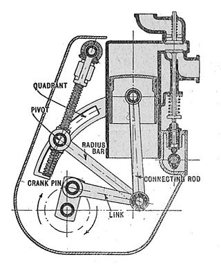
A straight-line mechanism is a mechanism that converts any type of rotary or angular motion to perfect or near-perfect straight-line motion, or vice versa. Straight-line motion is linear motion of definite length or "stroke", every forward stroke being followed by a return stroke, giving reciprocating motion. The first such mechanism, patented in 1784 by James Watt, produced approximate straight-line motion, referred to by Watt as parallel motion.

In kinematics, cognate linkages are linkages that ensure the same coupler curve geometry or input-output relationship, while being dimensionally dissimilar. In case of four-bar linkage coupler cognates, the Roberts–Chebyshev Theorem, after Samuel Roberts and Pafnuty Chebyshev, states that each coupler curve can be generated by three different four-bar linkages. These four-bar linkages can be constructed using similar triangles and parallelograms, and the Cayley diagram.

The Klannlinkage is a planar mechanism designed to simulate the gait of legged animal and function as a wheel replacement, a leg mechanism. The linkage consists of the frame, a crank, two grounded rockers, and two couplers all connected by pivot joints. It was developed by Joe Klann in 1994 as an expansion of Burmester curves which are used to develop four-bar double-rocker linkages such as harbor crane booms. It is categorized as a modified Stephenson type III kinematic chain.

In engineering, a mechanism is a device that transforms input forces and movement into a desired set of output forces and movement. Mechanisms generally consist of moving components which may include:

A revolute joint is a one-degree-of-freedom kinematic pair used frequently in mechanisms and machines. The joint constrains the motion of two bodies to pure rotation along a common axis. The joint does not allow translation, or sliding linear motion, a constraint not shown in the diagram. Almost all assemblies of multiple moving bodies include revolute joints in their designs. Revolute joints are used in numerous applications such as door hinges, mechanisms, and other uni-axial rotation devices.
A mechanical joint is a section of a machine which is used to connect one or more mechanical part to another. Mechanical joints may be temporary or permanent, most types are designed to be disassembled. Most mechanical joints are designed to allow relative movement of these mechanical parts of the machine in one degree of freedom, and restrict movement in one or more others.

In kinematics, an eight-bar linkage is a mechanism with one degree of freedom that is constructed from eight links and ten joints. These linkages are rare compared to four-bar and six-bar linkages, but two well-known examples are the Peaucellier linkage and the linkage designed by Theo Jansen for his walking machines.
A quick return mechanism is an apparatus to produce a reciprocating motion in which the time taken for travel in return stroke is less than in the forward stroke. It is driven by a circular motion source and uses a system of links with three turning pairs and a sliding pair. A quick-return mechanism is a subclass of a slider-crank linkage, with an offset crank.

A slider-crank linkage is a four-link mechanism with three revolute joints and one prismatic, or sliding, joint. The rotation of the crank drives the linear movement of the slider, or the expansion of gases against a sliding piston in a cylinder can drive the rotation of the crank.
In mechanical engineering, kinematic synthesis determines the size and configuration of mechanisms that shape the flow of power through a mechanical system, or machine, to achieve a desired performance. The word synthesis refers to combining parts to form a whole. Hartenberg and Denavit describe kinematic synthesis as
...it is design, the creation of something new. Kinematically, it is the conversion of a motion idea into hardware.


