
A ceramic is any of the various hard, brittle, heat-resistant, and corrosion-resistant materials made by shaping and then firing an inorganic, nonmetallic material, such as clay, at a high temperature. Common examples are earthenware, porcelain, and brick.

A lens is a transmissive optical device that focuses or disperses a light beam by means of refraction. A simple lens consists of a single piece of transparent material, while a compound lens consists of several simple lenses (elements), usually arranged along a common axis. Lenses are made from materials such as glass or plastic and are ground, polished, or molded to the required shape. A lens can focus light to form an image, unlike a prism, which refracts light without focusing. Devices that similarly focus or disperse waves and radiation other than visible light are also called "lenses", such as microwave lenses, electron lenses, acoustic lenses, or explosive lenses.

A corrective lens is a transmissive optical device that is worn on the eye to improve visual perception. The most common use is to treat refractive errors: myopia, hypermetropia, astigmatism, and presbyopia. Glasses or "spectacles" are worn on the face a short distance in front of the eye. Contact lenses are worn directly on the surface of the eye. Intraocular lenses are surgically implanted most commonly after cataract removal but can be used for purely refractive purposes.

Injection moulding is a manufacturing process for producing parts by injecting molten material into a mould, or mold. Injection moulding can be performed with a host of materials mainly including metals, glasses, elastomers, confections, and most commonly thermoplastic and thermosetting polymers. Material for the part is fed into a heated barrel, mixed, and injected into a mould cavity, where it cools and hardens to the configuration of the cavity. After a product is designed, usually by an industrial designer or an engineer, moulds are made by a mould-maker from metal, usually either steel or aluminium, and precision-machined to form the features of the desired part. Injection moulding is widely used for manufacturing a variety of parts, from the smallest components to entire body panels of cars. Advances in 3D printing technology, using photopolymers that do not melt during the injection moulding of some lower-temperature thermoplastics, can be used for some simple injection moulds.
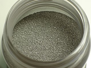
Powder metallurgy (PM) is a term covering a wide range of ways in which materials or components are made from metal powders. PM processes can reduce or eliminate the need for subtractive processes in manufacturing, lowering material losses and reducing the cost of the final product.
Fibre-reinforced plastic is a composite material made of a polymer matrix reinforced with fibres. The fibres are usually glass, carbon, aramid, or basalt. Rarely, other fibres such as paper, wood, boron, or asbestos have been used. The polymer is usually an epoxy, vinyl ester, or polyester thermosetting plastic, though phenol formaldehyde resins are still in use.
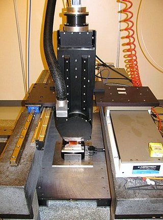
Diamond turning is turning using a cutting tool with a diamond tip. It is a process of mechanical machining of precision elements using lathes or derivative machine tools equipped with natural or synthetic diamond-tipped tool bits. The term single-point diamond turning (SPDT) is sometimes applied, although as with other lathe work, the "single-point" label is sometimes only nominal. The process of diamond turning is widely used to manufacture high-quality aspheric optical elements from crystals, metals, acrylic, and other materials. Plastic optics are frequently molded using diamond turned mold inserts. Optical elements produced by the means of diamond turning are used in optical assemblies in telescopes, video projectors, missile guidance systems, lasers, scientific research instruments, and numerous other systems and devices. Most SPDT today is done with computer numerical control (CNC) machine tools. Diamonds also serve in other machining processes, such as milling, grinding, and honing. Diamond turned surfaces have a high specular brightness and require no additional polishing or buffing, unlike other conventionally machined surfaces.

Compression molding is a method of molding in which the molding material, generally preheated, is first placed in an open, heated mold cavity. The mold is closed with a top force or plug member, pressure is applied to force the material into contact with all mold areas, while heat and pressure are maintained until the molding material has cured; this process is known as compression molding method and in case of rubber it is also known as 'Vulcanisation'. The process employs thermosetting resins in a partially cured stage, either in the form of granules, putty-like masses, or preforms.

Blow molding is a manufacturing process for forming hollow plastic parts. It is also used for forming glass bottles or other hollow shapes.

An end mill is a type of milling cutter, a cutting tool used in industrial milling applications. It is distinguished from the drill bit in its application, geometry, and manufacture. While a drill bit can only cut in the axial direction, most milling bits can cut in the radial direction. Not all mills can cut axially; those designed to cut axially are known as end mills.

An aspheric lens or asphere is a lens whose surface profiles are not portions of a sphere or cylinder. In photography, a lens assembly that includes an aspheric element is often called an aspherical lens.

An optical fiber, or optical fibre, is a flexible glass or plastic fiber that can transmit light from one end to the other. Such fibers find wide usage in fiber-optic communications, where they permit transmission over longer distances and at higher bandwidths than electrical cables. Fibers are used instead of metal wires because signals travel along them with less loss and are immune to electromagnetic interference. Fibers are also used for illumination and imaging, and are often wrapped in bundles so they may be used to carry light into, or images out of confined spaces, as in the case of a fiberscope. Specially designed fibers are also used for a variety of other applications, such as fiber optic sensors and fiber lasers.

Compact disc manufacturing is the process by which commercial compact discs (CDs) are replicated in mass quantities using a master version created from a source recording. This may be either in audio form (CD-DA) or data form (CD-ROM). This process is used in the mastering of read-only compact discs. DVDs and Blu-rays use similar methods.
Optical lens design is the process of designing a lens to meet a set of performance requirements and constraints, including cost and manufacturing limitations. Parameters include surface profile types, as well as radius of curvature, distance to the next surface, material type and optionally tilt and decenter. The process is computationally intensive, using ray tracing or other techniques to model how the lens affects light that passes through it.
Optical manufacturing and testing is the process of manufacturing and testing optical components. It spans a wide range of manufacturing procedures and optical test configurations.

A diamond tool is a cutting tool with diamond grains fixed on the functional parts of the tool via a bonding material or another method. As diamond is a superhard material, diamond tools have many advantages as compared with tools made with common abrasives such as corundum and silicon carbide.
Glass production involves two main methods – the float glass process that produces sheet glass, and glassblowing that produces bottles and other containers. It has been done in a variety of ways during the history of glass.
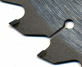
Cemented carbides are a class of hard materials used extensively for cutting tools, as well as in other industrial applications. It consists of fine particles of carbide cemented into a composite by a binder metal. Cemented carbides commonly use tungsten carbide (WC), titanium carbide (TiC), or tantalum carbide (TaC) as the aggregate. Mentions of "carbide" or "tungsten carbide" in industrial contexts usually refer to these cemented composites.
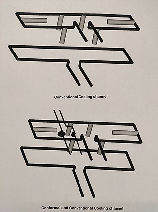
Conformal cooling channel is a cooling passageway which follows the shape or profile of the mould core or cavity to perform rapid uniform cooling process for injection moulding or blow moulding processes.
3D metal moulding, also referred to as metal injection moulding or (MIM), is used to manufacture components with complex geometries. The process uses a mixture of metal powders and polymer binders – also known as "feedstock" – which are then injection moulded.


