Straight-line mechanism

Last updated
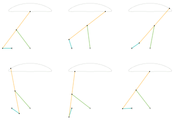
Animation of Watt's Linkage Watts Linkage.gif
Animation of Watt's Linkage
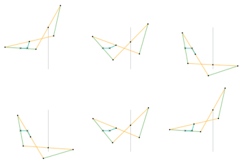
Roberts Linkage.
Links of the same color are the same length. Roberts Linkage.gif
Roberts Linkage.
Links of the same color are the same length.
Sarrus Linkage.
Parts of the same color are the same dimensions. Sarrus Linkage.gif
Sarrus Linkage.
Parts of the same color are the same dimensions.
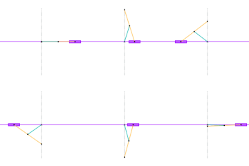
Peaucellier-Lipkin Inversor.
Links of the same color are the same length. Peaucellier-Lipkin Inversor.gif
Peaucellier-Lipkin Inversor.
Links of the same color are the same length.

A straight-line mechanism is a mechanism that converts any type of rotary or angular motion to perfect or near-perfect straight-line motion, or vice versa. Straight-line motion is linear motion of definite length or "stroke", every forward stroke being followed by a return stroke, giving reciprocating motion. The first such mechanism, patented in 1784 by James Watt, produced approximate straight-line motion, referred to by Watt as parallel motion.

Contents

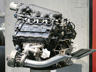
Straight-line mechanisms are used in a variety of applications, such as engines, vehicle suspensions, walking robots, and rover wheels.[ citation needed ]

History

In the late eighteenth century, before the development of the planer and the milling machine, it was extremely difficult to machine straight, flat surfaces. During that era, much thought was given to the problem of attaining a straight-line motion, as this would allow the flat surfaces to be machined. To find a solution to the problem, the first straight line mechanism was developed by James Watt, for guiding the piston of early steam engines. Although it does not generate an exact straight line, a good approximation is achieved over a considerable distance of travel.

Perfect straight line linkages were later discovered in the nineteenth century, but they weren't as needed, as by then other techniques for machining had been developed.[ citation needed ]

List of linkages

Approximate straight line linkages

These mechanisms often utilize four bar linkages as they require very few pieces. These four-bar linkages have coupler curves that have one or more regions of approximately perfect straight line motion. The exception in this list is Watt's parallel motion, which combines Watt's linkage with another four-bar linkage – the pantograph – to amplify the existing approximate straight line movement.

It is not possible to create perfectly straight line motion using a four-bar linkage, without using a prismatic joint.

Perfect straight line linkages

Eventually, perfect straight line motion would be achieved.

The Sarrus linkage was the first perfect linear linkage, made in 1853. However, it is a spatial linkage rather than a planar linkage. The first planar linkage would not be made until 1864.

Currently, all planar linkages which produce perfect linear motion utilize the inversion around a circle to produce a hypothetical circle of infinite radius, which is a line. This is why they are called inversors or inversor cells.
The simplest solutions are Hart's W-frame – which use 6-bars – and the Quadruplanar inversors – Sylvester-Kempe and Kumara-Kampling, which also use 6-bars.

The Scott Russell linkage (1803) translates linear motion through a right angle, but is not a straight line mechanism in itself. The Grasshopper beam/Evans linkage, an approximate straight line linkage, and the Bricard linkage, an exact straight line linkage, share similarities with the Scott Russell linkage and the Trammel of Archimedes.

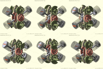
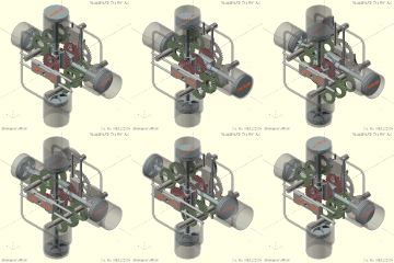
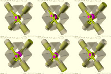
Compound eccentric mechanisms with elliptical motion

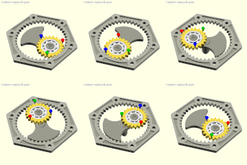
These mechanisms use the principle of a rolling curve instead of a coupler curve and can convert continuous, rather than just limited, rotary motion to reciprocating motion and vice versa via elliptical motion. The straight-line sinusoidal motion produces no second-order inertial forces, which simplifies balancing in high-speed machines.

Approximate straight line linkages

Parts/links of the same color are the same dimensions.

Perfect straight line linkages

Parts/links of the same color are the same dimensions.

Tusi couple, elliptical motion: versions and inversions

Compound eccentric mechanisms with elliptical motion

See also

Notes

  1. 1 2 3 4 5 6 7 8 9 Linkage has unstable positions that are not accounted for. Mitigations for said unstable positions are not shown for the sake of clarity.

Related Research Articles

<span class="mw-page-title-main">Machine</span> Powered mechanical device

A machine is a physical system that uses power to apply forces and control movement to perform an action. The term is commonly applied to artificial devices, such as those employing engines or motors, but also to natural biological macromolecules, such as molecular machines. Machines can be driven by animals and people, by natural forces such as wind and water, and by chemical, thermal, or electrical power, and include a system of mechanisms that shape the actuator input to achieve a specific application of output forces and movement. They can also include computers and sensors that monitor performance and plan movement, often called mechanical systems.

<span class="mw-page-title-main">Parallel motion linkage</span> Six-bar straight-line mechanism

In kinematics, the parallel motion linkage is a six-bar mechanical linkage invented by the Scottish engineer James Watt in 1784 for the double-acting Watt steam engine. It allows a rod moving practically straight up and down to transmit motion to a beam moving in an arc, without putting significant sideways strain on the rod.
<span class="mw-page-title-main">Watt's linkage</span> Four-bar straight-line mechanism

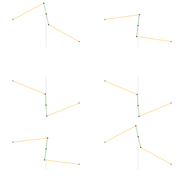
In kinematics, Watt's linkage is a type of mechanical linkage invented by James Watt in which the central moving point of the linkage is constrained to travel on a nearly straight line. It was described in Watt's patent specification of 1784 for the Watt steam engine.

<span class="mw-page-title-main">Four-bar linkage</span> Mechanical linkage consisting of four links connected by joints in a loop

In the study of mechanisms, a four-bar linkage, also called a four-bar, is the simplest closed-chain movable linkage. It consists of four bodies, called bars or links, connected in a loop by four joints. Generally, the joints are configured so the links move in parallel planes, and the assembly is called a planar four-bar linkage. Spherical and spatial four-bar linkages also exist and are used in practice.
<span class="mw-page-title-main">Linkage (mechanical)</span> Assembly of systems connected to manage forces and movement

A mechanical linkage is an assembly of systems connected to manage forces and movement. The movement of a body, or link, is studied using geometry so the link is considered to be rigid. The connections between links are modeled as providing ideal movement, pure rotation or sliding for example, and are called joints. A linkage modeled as a network of rigid links and ideal joints is called a kinematic chain.

<span class="mw-page-title-main">Peaucellier–Lipkin linkage</span> Mechanical linkage capable of transforming rotary motion into linear motion

The Peaucellier–Lipkin linkage, invented in 1864, was the first true planar straight line mechanism – the first planar linkage capable of transforming rotary motion into perfect straight-line motion, and vice versa. It is named after Charles-Nicolas Peaucellier (1832–1913), a French army officer, and Yom Tov Lipman Lipkin (1846–1876), a Lithuanian Jew and son of the famed Rabbi Israel Salanter.
<span class="mw-page-title-main">Overconstrained mechanism</span> Moveable linkage with zero mobility

In mechanical engineering, an overconstrained mechanism is a linkage that has more degrees of freedom than is predicted by the mobility formula. The mobility formula evaluates the degree of freedom of a system of rigid bodies that results when constraints are imposed in the form of joints between the links.

<span class="mw-page-title-main">Chebyshev lambda linkage</span> Four-bar straight-line mechanism

In kinematics, the Chebyshev Lambda Linkage is a four-bar linkage that converts rotational motion to approximate straight-line motion with approximate constant velocity. It is so-named because it looks like a lowercase Greek letter lambda (λ). The precise design trades off straightness, lack of acceleration, and the proportion of the driving rotation that is spent in the linear portion of the full curve.

<span class="mw-page-title-main">Tusi couple</span> Mathematical device

The Tusi couple is a mathematical device in which a small circle rotates inside a larger circle twice the diameter of the smaller circle. Rotations of the circles cause a point on the circumference of the smaller circle to oscillate back and forth in linear motion along a diameter of the larger circle. The Tusi couple is a 2-cusped hypocycloid.
<span class="mw-page-title-main">Antiparallelogram</span> Polygon with four crossed edges of two lengths

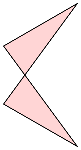
In geometry, an antiparallelogram is a type of self-crossing quadrilateral. Like a parallelogram, an antiparallelogram has two opposite pairs of equal-length sides, but these pairs of sides are not in general parallel. Instead, each pair of sides is antiparallel with respect to the other, with sides in the longer pair crossing each other as in a scissors mechanism. Whereas a parallelogram's opposite angles are equal and oriented the same way, an antiparallelogram's are equal but oppositely oriented. Antiparallelograms are also called contraparallelograms or crossed parallelograms.

The following outline is provided as an overview of and topical guide to machines:

<span class="mw-page-title-main">Scott Russell linkage</span> Type of straight line mechanism

A Scott Russell linkage is a linkage which translates linear motion through a right angle.

<span class="mw-page-title-main">Sarrus linkage</span> Six-bar straight-line mechanism

The Sarrus linkage, invented in 1853 by Pierre Frédéric Sarrus, is a mechanical linkage to convert a limited circular motion to a linear motion or vice versa without reference guideways. It is a spatial six-bar linkage (6R) with two groups of three parallel adjacent joint-axes.

<span class="mw-page-title-main">Chebyshev linkage</span> Four-bar straight-line mechanism

In kinematics, Chebyshev's linkage is a four-bar linkage that converts rotational motion to approximate linear motion.

<span class="mw-page-title-main">Cognate linkage</span> Linkages of different dimensions with the same output motion

In kinematics, cognate linkages are linkages that ensure the same coupler curve geometry or input-output relationship, while being dimensionally dissimilar. In case of four-bar linkage coupler cognates, the Roberts–Chebyshev Theorem, after Samuel Roberts and Pafnuty Chebyshev, states that each coupler curve can be generated by three different four-bar linkages. These four-bar linkages can be constructed using similar triangles and parallelograms, and the Cayley diagram.

<span class="mw-page-title-main">Mechanism (engineering)</span> Device used to transfer forces via non-electric means

In engineering, a mechanism is a device that transforms input forces and movement into a desired set of output forces and movement. Mechanisms generally consist of moving components which may include:

<span class="mw-page-title-main">Trammel of Archimedes</span> Ellipse-drawing mechanism

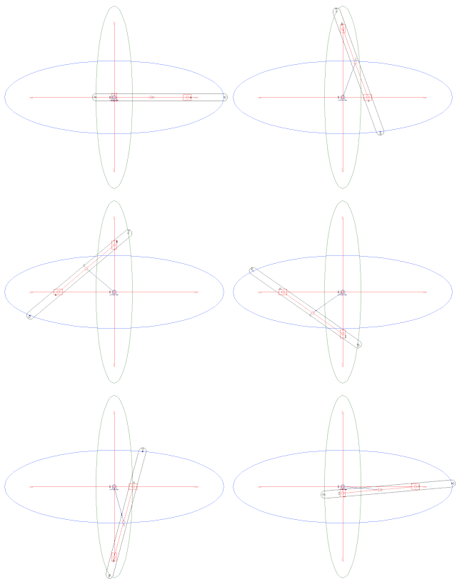
A trammel of Archimedes is a mechanism that generates the shape of an ellipse. It consists of two shuttles which are confined ("trammeled") to perpendicular channels or rails and a rod which is attached to the shuttles by pivots at fixed positions along the rod.
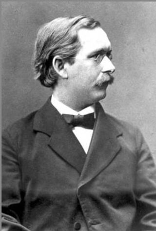
<span class="mw-page-title-main">Ludwig Burmester</span> German kinematician and geometer (1840–1927)

Ludwig Ernst Hans Burmester was a German kinematician and geometer.

<span class="mw-page-title-main">Hart's inversors</span> Planar straight-line mechanisms

Hart's inversors are two planar mechanisms that provide a perfect straight line motion using only rotary joints. They were invented and published by Harry Hart in 1874–5.
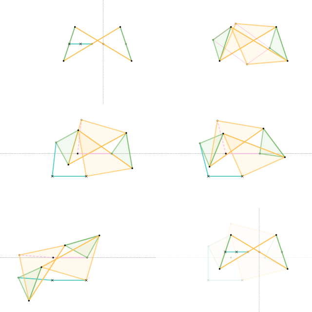
<span class="mw-page-title-main">Quadruplanar inversor</span> Mechanism that provides a perfect straight line motion without sliding guides

The Quadruplanar inversor of Sylvester and Kempe is a generalization of Hart's inversor. Like Hart's inversor, is a mechanism that provides a perfect straight line motion without sliding guides.

References

  1. Kempe, Alfred Bray (1877). How to Draw a Straight Line: A Lecture on Linkages. Macmillan and Company. ISBN   978-1-4297-0244-7.
  2. Artobolevsky, Ivan Ivanovich. Mechanisms in modern engineering design. ISBN   978-5-9710-5698-0.
  3. Four-cylinder, Four-cycle Engine With Two Reciprocating Components, A.J.S Baker, M.E Cross, The Institution of Mechanical Engineers, Automobile Division, Volume 188 38/74
  4. Parsons' epicyclic engine
  5. Patent No. DE 3232974, published March 1984
  6. Patent Application No. US 628 248, July 1984 (see US 4 641 611)
  7. Clean engines - A combination of advanced materials and a new engine design