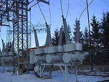
An SF6 circuit breaker rated 115kV, 1200A installed at a hydroelectric generating station
Sulfur hexafluoride circuit breakers protect electrical power stations and distribution systems by interrupting electric currents, when tripped by a protective relay. Instead of oil, air, or a vacuum, a sulfur hexafluoride circuit breaker uses sulfur hexafluoride (SF6) gas to cool and quench the arc on opening a circuit. Advantages over other media include lower operating noise and no emission of hot gases, and relatively low maintenance. Developed in the 1950s and onward, SF6 circuit breakers are widely used in electrical grids at transmission voltages up to 800 kV, as generator circuit breakers, and in distribution systems at voltages up to 35 kV.
Sulfur hexafluoride circuit breakers may be used as self-contained apparatus in outdoor air-insulated substations or may be incorporated into gas-insulated switchgear which allows compact installations at high voltages.
Operating principle
Current interruption in a high-voltage circuit breaker is obtained by separating two contacts in a medium, such as sulfur hexafluoride (SF6), having excellent dielectric and arc-quenching properties. After contact separation, current is carried through an arc and is interrupted when this arc is cooled by a gas blast of sufficient intensity.[1]
SF6 gas is electronegative and has a strong tendency to absorb free electrons. The contacts of the breaker are opened in a high-pressure flow of sulfur hexafluoride gas, and an arc is struck between them. The gas captures the conducting free electrons in the arc to form relatively immobile negative ions. This loss of conducting electrons in the arc quickly builds up enough insulation strength to extinguish the arc.
A gas blast applied to the arc must be able to cool it rapidly so that gas temperature between the contacts is reduced from 20,000K to less than 2000K in a few hundred microseconds, so that it is able to withstand the transient recovery voltage that is applied across the contacts after current interruption. Sulfur hexafluoride is generally used in present high-voltage circuit breakers at rated voltage higher than 52kV.
Into the 1980s, the pressure necessary to blast the arc was generated mostly by gas heating using arc energy. It is now possible to use low-energy spring-loaded mechanisms to drive high-voltage circuit breakers up to 800kV.
Brief history
High-voltage circuit breakers have changed since they were introduced in the mid-1950s, and several interrupting principles have been developed that have contributed successively to a large reduction of the operating energy. These breakers are available for indoor or outdoor applications, the latter being in the form of breaker poles housed in ceramic insulators mounted on a structure. The first patents on the use of SF6 as an interrupting medium were filed in Germany in 1938 by Vitaly Grosse (AEG) and independently later in the United States in July 1951 by H. J. Lingal, T. E. Browne and A. P. Strom (Westinghouse).
The first industrial application of SF6 for current interruption dates to 1953. High-voltage 15kV to 161kV load switches were developed with a breaking capacity of 600A. The first high-voltage SF6 circuit breaker built in 1956 by Westinghouse, could interrupt 5kA under 115kV, but it had six interrupting chambers in series per pole.
In 1957, the puffer-type technique was introduced for SF6 circuit breakers, wherein the relative movement of a piston and a cylinder linked to the moving part is used to generate the pressure rise necessary to blast the arc via a nozzle made of insulating material. In this technique, the pressure rise is obtained mainly by gas compression.
The first high-voltage SF6 circuit breaker with a high short-circuit current capability was produced by Westinghouse in 1959. This circuit breaker in a grounded tank (called a dead tank), could interrupt 41.8kA under 138kV (10,000MV·A) and 37.6kA under 230kV (15,000 MV·A). This performance was already significant, but the three chambers per pole and the high-pressure source needed for the blast (1.35MPa) was a constraint that had to be avoided in subsequent developments.
The excellent properties of SF6 led to the fast extension of this technique in the 1970s and to its use for the development of circuit breakers with high interrupting capability, up to 800kV.
Gas circuit breaker operation. Orange and red areas show high-pressure gas produced by motion of the breaker components.
The achievement around 1983 of the first single-break 245kV and the corresponding 420kV to 550kV and 800kV, with respectively 2, 3, and 4 chambers per pole, led to the dominance of SF6 circuit breakers in the complete range of high voltages.
Several characteristics of SF6 circuit breakers can explain their success:
Simplicity of the interrupting chamber which does not need an auxiliary breaking chamber
Autonomy provided by the puffer technique
The possibility to obtain the highest performance, up to 63kA, with a reduced number of interrupting chambers
Short break time of 2 to 2.5 cycles
High electrical endurance, allowing at least 25 years of operation without reconditioning
Integrated closing resistors or synchronized operations to reduce switching over-voltages
Reliability and availability
Low noise levels
The reduction in the number of interrupting chambers per pole has led to a considerable simplification of circuit breakers as well as the number of parts and seals required. As a direct consequence, the reliability of circuit breakers improved, as verified later on by International Council on Large Electric Systems (CIGRE) surveys.
Design features
Thermal blast chambers
New types of SF6 breaking chambers, which implement innovative interrupting principles, have been developed over the past 30 years,[when?] with the objective of reducing the operating energy of the circuit breaker. One aim of this evolution was to further increase the reliability by reducing the dynamic forces in the pole. Developments since 1980 have seen the use of the self-blast technique of interruption for SF6 interrupting chambers.
These developments have been facilitated by the progress made in digital simulations that were widely used to optimize the geometry of the interrupting chamber and the linkage between the poles and the mechanism.
This technique has proved to be very efficient and has been widely applied for high-voltage circuit breakers up to 550kV. It has allowed the development of new ranges of circuit breakers operated by low energy spring-operated mechanisms.
Auto-blast circuit breaker
The reduction of operating energy was mainly achieved by lowering energy used for gas compression and by making increased use of arc energy to produce the pressure necessary to quench the arc and obtain current interruption. Low current interruption, up to about 30% of rated short-circuit current, is obtained by a puffer blast. Also includes more of extensive energy available .
Self-blast chambers
Further development in the thermal blast technique was made by the introduction of a valve between the expansion and compression volumes. When interrupting low currents the valve opens under the effect of the overpressure generated in the compression volume. The blow-out of the arc is made as in a puffer circuit breaker thanks to the compression of the gas obtained by the piston action. In the case of high currents interruption, the arc energy produces a high overpressure in the expansion volume, which leads to the closure of the valve and thus isolating the expansion volume from the compression volume. The overpressure necessary for breaking is obtained by the optimal use of the thermal effect and of the nozzle clogging effect produced whenever the cross-section of the arc significantly reduces the exhaust of gas in the nozzle. In order to avoid excessive energy consumption by gas compression, a valve is fitted on the piston in order to limit the overpressure in the compression to a value necessary for the interruption of low short circuit currents.
Self-blast circuit breaker chamber (1) closed, (2) interrupting low current, (3) interrupting high current, and (4) open.
This technique, known as "self-blast" has now been used extensively since 1980 for the development of many types of interrupting chambers. The increased understanding of arc interruption obtained by digital simulations and validation through breaking tests, contribute to a higher reliability of these self-blast circuit breakers. In addition the reduction in operating energy, allowed by the self-blast technique, leads to longer service life.
Double motion of contacts
An important decrease in operating energy can also be obtained by reducing the kinetic energy consumed during the tripping operation. One way is to displace the two arcing contacts in opposite directions so that the arc speed is half that of a conventional layout with a single mobile contact.
The thermal and self-blast principles have enabled the use of low-energy spring mechanisms for the operation of high-voltage circuit breakers. They progressively replaced the puffer technique in the 1980s; first in 72.5kV breakers, and then from 145kV to 800kV.
Comparison of single motion and double motion techniques
The double motion technique halves the tripping speed of the moving part. In principle, the kinetic energy could be quartered if the total moving mass were not increased. However, as the total moving mass is increased, the practical reduction in kinetic energy is closer to 60%. The total tripping energy also includes the compression energy, which is almost the same for both techniques. Thus, the reduction of the total tripping energy is lower, about 30%, although the exact value depends on the application and the operating mechanism. Depending on the specific case, either the double motion or the single motion technique can be cheaper. Other considerations, such as rationalization of the circuit breaker range, can also influence the cost.
Thermal blast chamber with arc-assisted opening
In this interruption principle arc energy is used, on the one hand to generate the blast by thermal expansion and, on the other hand, to accelerate the moving part of the circuit breaker when interrupting high currents. The overpressure produced by the arc energy downstream of the interruption zone is applied on an auxiliary piston linked with the moving part. The resulting force accelerates the moving part, thus increasing the energy available for tripping. With this interrupting principle it is possible, during high-current interruptions, to increase by about 30% the tripping energy delivered by the operating mechanism and to maintain the opening speed independently of the current. It is obviously better suited to circuit breakers with high breaking currents, such as generator circuit breakers.
Generator circuit breakers
Generator circuit breaker rated for 17.5kV and 63kA
Generator circuit breakers (GCB) are connected between a generator and the step-up voltage transformer. They are generally used at the outlet of high-power generators (30MVA to 1800MVA) in order to protect them in a reliable, fast and economic manner. Such circuit breakers have high carrying current rating (4kA to 40kA), and have a high breaking capacity (50kA to 275kA).
They belong to the medium voltage range, but the transient recovery voltage withstand capability required by IEC/IEEE 62771-37-013 is such that the specifically developed interrupting principles must be used. A particular embodiment of the thermal blast technique has been developed and applied to generator circuit breakers. The self-blast technique described above is also widely used in SF6 generator circuit breakers, in which the contact system is driven by a low-energy, spring-operated mechanism. An example of such a device is shown in the figure below; this circuit breaker is rated for 17.5kV and 63kA.
High-power testing
The short-circuit interrupting capability of high-voltage circuit breakers is such that it cannot be demonstrated with a single source able to generate the necessary power. A special scheme is used with a generator that provides the short-circuit current until current interruption and afterwards a voltage source applies the recovery voltage across the terminals of the circuit breaker. Tests are usually performed single-phase, but can also be performed three-phase[2] Also have a small control of power.
Issues related to SF6 circuit breakers
The following issues are associated with SF6 circuit breakers:
Toxic lower order gases
When an arc is formed in SF6 gas small quantities of lower order gases are formed. Some of these byproducts are toxic and can cause irritation to eyes and respiratory systems. This is a concern if the interrupters are opened for maintenance or at disposal of the interrupters.
Oxygen displacement
SF6 is heavier than air, so care must be taken when entering low confined spaces due to the risk of oxygen displacement.
Some governments have implemented systems to monitor and control the emission of SF6 to the atmosphere.[4]
Comparison with other types
Circuit breakers are usually classed on their insulating medium. The follow types of circuit breakers may be an alternative to SF6 types.
air-blast
oil
vacuum
CO2
Compared with air-blast breakers, operation with SF6 is quieter and no hot gases are discharged in normal operation. No compressed-air plant is required to maintain blast air pressure. The higher dielectric strength of the gas allows more compact design or a larger interrupting rating for the same relative size as air-blast circuit breakers. This also has the desirable effect of minimizing size and weight of the circuit breakers, making foundations and installation less costly. Operating mechanisms are simpler, and less maintenance is required, generally with more mechanical operations allowed between inspections or maintenance. However, checking or replacing the SF6 gas requires special equipment and training to prevent accidental emissions. At very low outdoor temperatures, unlike air, SF6 gas can liquefy, reducing the ability of the circuit breaker to interrupt fault currents.
Oil-filled breakers contain some volume of mineral oil. A minimum-oil breaker may contain on the order of hundreds of litres of oil at transmission voltages; a dead-tank bulk oil-filled circuit breaker may contain tens of thousands of litres of oil. If this is discharged from the circuit breaker during a failure, it will be a fire hazard. Oil is also toxic to water systems and leakages must be carefully contained.
Vacuum circuit breakers have limited availability and are not made for transmission voltages, unlike SF6 breakers available up to 800 kV.
An electrical insulator is a material in which electric current does not flow freely. The atoms of the insulator have tightly bound electrons which cannot readily move. Other materials—semiconductors and conductors—conduct electric current more easily. The property that distinguishes an insulator is its resistivity; insulators have higher resistivity than semiconductors or conductors. The most common examples are non-metals.
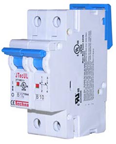
A circuit breaker is an electrical safety device designed to protect an electrical circuit from damage caused by overcurrent. Its basic function is to interrupt current flow to protect equipment and to prevent the risk of fire. Unlike a fuse, which operates once and then must be replaced, a circuit breaker can be reset to resume normal operation.
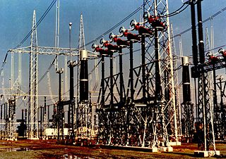
A substation is a part of an electrical generation, transmission, and distribution system. Substations transform voltage from high to low, or the reverse, or perform any of several other important functions. Between the generating station and consumer, electric power may flow through several substations at different voltage levels. A substation may include transformers to change voltage levels between high transmission voltages and lower distribution voltages, or at the interconnection of two different transmission voltages. They are a common component of the infrastructure. There are 55,000 substations in the United States.
Sulfur hexafluoride or sulphur hexafluoride (British spelling) is an inorganic compound with the formula SF6. It is a colorless, odorless, non-flammable, and non-toxic gas. SF 6 has an octahedral geometry, consisting of six fluorine atoms attached to a central sulfur atom. It is a hypervalent molecule.
In electronics and electrical engineering, a fuse is an electrical safety device that operates to provide overcurrent protection of an electrical circuit. Its essential component is a metal wire or strip that melts when too much current flows through it, thereby stopping or interrupting the current. It is a sacrificial device; once a fuse has operated, it is an open circuit, and must be replaced or rewired, depending on its type.
In electronics, electrical breakdown or dielectric breakdown is a process that occurs when an electrically insulating material, subjected to a high enough voltage, suddenly becomes a conductor and current flows through it. All insulating materials undergo breakdown when the electric field caused by an applied voltage exceeds the material's dielectric strength. The voltage at which a given insulating object becomes conductive is called its breakdown voltage and, in addition to its dielectric strength, depends on its size and shape, and the location on the object at which the voltage is applied. Under sufficient voltage, electrical breakdown can occur within solids, liquids, or gases. However, the specific breakdown mechanisms are different for each kind of dielectric medium.
High voltage electricity refers to electrical potential large enough to cause injury or damage. In certain industries, high voltage refers to voltage above a certain threshold. Equipment and conductors that carry high voltage warrant special safety requirements and procedures.
An electric arc is an electrical breakdown of a gas that produces a prolonged electrical discharge. The current through a normally nonconductive medium such as air produces a plasma, which may produce visible light. An arc discharge is initiated either by thermionic emission or by field emission. After initiation, the arc relies on thermionic emission of electrons from the electrodes supporting the arc. An arc discharge is characterized by a lower voltage than a glow discharge. An archaic term is voltaic arc, as used in the phrase "voltaic arc lamp".
In electric power distribution, automatic circuit reclosers (ACRs) are a class of switchgear designed for use on overhead electricity distribution networks to detect and interrupt transient faults. Also known as reclosers or autoreclosers, ACRs are essentially rated circuit breakers with integrated current and voltage sensors and a protection relay, optimized for use as a protection asset. Commercial ACRs are governed by the IEC 62271-111/IEEE Std C37.60 and IEC 62271-200 standards. The three major classes of operating maximum voltage are 15.5 kV, 27 kV and 38 kV.
In an electric power system, a switchgear is composed of electrical disconnect switches, fuses or circuit breakers used to control, protect and isolate electrical equipment. Switchgear is used both to de-energize equipment to allow work to be done and to clear faults downstream. This type of equipment is directly linked to the reliability of the electricity supply.
A trigatron is a type of triggerable spark gap switch designed for high current and high voltage. It has very simple construction and in many cases is the lowest cost high energy switching option. It may operate in open air, it may be sealed, or it may be filled with a dielectric gas other than air or a liquid dielectric. The dielectric gas may be pressurized, or a liquid dielectric may be substituted to further extend the operating voltage. Trigatrons may be rated for repeated use, or they may be single-shot, destroyed in a single use.
Isidor Sauers (born 1948) is an Austrian-born American who is a physicist at the Oak Ridge National Laboratory in Tennessee. He is a specialist on the properties of Sulfur hexafluoride (SF6), with an important patent and over 60 peer-reviewed academic papers.
An arc flash is the light and heat produced as part of an arc fault, a type of electrical explosion or discharge that results from a connection through air to ground or another voltage phase in an electrical system.
An electric power system is a network of electrical components deployed to supply, transfer, and use electric power. An example of a power system is the electrical grid that provides power to homes and industries within an extended area. The electrical grid can be broadly divided into the generators that supply the power, the transmission system that carries the power from the generating centers to the load centers, and the distribution system that feeds the power to nearby homes and industries.
Copper–tungsten is a mixture of copper and tungsten. As copper and tungsten are not mutually soluble, the material is composed of distinct particles of one metal dispersed in a matrix of the other one. The microstructure is therefore rather a metal matrix composite instead of a true alloy.
A dielectric gas, or insulating gas, is a dielectric material in gaseous state. Its main purpose is to prevent or rapidly quench electric discharges. Dielectric gases are used as electrical insulators in high voltage applications, e.g. transformers, circuit breakers, switchgear, radar waveguides, etc.
A hybrid switchgear is one that combines the components of traditional air-insulated switchgear (AIS) and SF6 gas-insulated switchgear (GIS) technologies. It is characterized by a compact and modular design, which encompasses several different functions in one module.
This glossary of electrical and electronics engineering is a list of definitions of terms and concepts related specifically to electrical engineering and electronics engineering. For terms related to engineering in general, see Glossary of engineering.
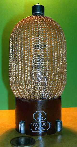
In electrical engineering, a vacuum interrupter is a switch which uses electrical contacts in a vacuum. It is the core component of medium-voltage circuit-breakers, generator circuit-breakers, and high-voltage circuit-breakers. Separation of the electrical contacts results in a metal vapour arc, which is quickly extinguished. Vacuum interrupters are widely used in utility power transmission systems, power generation unit, and power-distribution systems for railways, arc furnace applications, and industrial plants.
C4-FN (C4-fluoronitrile, C4FN) is a perfluorinated compound developed as a high-dielectric gas for high-voltage switchgear. It has the structure (CF3)2CFC≡N, which can be described as perfluoroisobutyronitrile, falling under the category of PFAS, or per- and polyfluoroalkyl substances.
This page is based on this Wikipedia article Text is available under the CC BY-SA 4.0 license; additional terms may apply. Images, videos and audio are available under their respective licenses.