Engine balance refers to how the inertial forces produced by moving parts in an internal combustion engine or steam engine are neutralised with counterweights and balance shafts, to prevent unpleasant and potentially damaging vibration. The strongest inertial forces occur at crankshaft speed (first-order forces) and balance is mandatory, while forces at twice crankshaft speed (second-order forces) can become significant in some cases.
Although some components within the engine (such as the connecting rods) have complex motions, all motions can be separated into reciprocating and rotating components, which assists in the analysis of imbalances.
Using the example of an inline engine (where the pistons are vertical), the main reciprocating motions are:
Pistons moving upwards/downwards
Connecting rods moving upwards/downwards
Connecting rods moving left/right as they rotate around the crankshaft, however the lateral vibrations caused by these movements are much smaller than the up–down vibrations caused by the pistons.[1]
While the main rotating motions that may cause imbalance are:
Crankshaft
Camshafts
Connecting rods (rotating around the piston end as required by the varying horizontal offset between the piston and the crank throw)
The imbalances can be caused by either the static mass of individual components or the cylinder layout of the engine, as detailed in the following sections.
Static mass
If the weight— or the weight distribution— of moving parts is not uniform, their movement can cause out-of-balance forces, leading to vibration. For example, if the weights of pistons or connecting rods are different between cylinders, the reciprocating motion can cause vertical forces. Similarly, the rotation of a crankshaft with uneven web weights or a flywheel with an uneven weight distribution can cause a rotating unbalance.
Cylinder layout
Even with a perfectly balanced weight distribution of the static masses, some cylinder layouts cause imbalance due to the forces from each cylinder not cancelling each other out at all times. For example, an inline-four engine has a vertical vibration (at twice the engine speed). These imbalances are inherent in the design and unable to be avoided, therefore the resulting vibration needs to be managed using balance shafts or other NVH-reduction techniques to minimise the vibration that enters the cabin.
Types of imbalance
Reciprocating imbalance
A reciprocating imbalance is caused when the linear motion of a component (such as a piston) is not cancelled out by another component moving with equal momentum, but opposite in direction on the same plane.
Types of reciprocating phase imbalance are:
Mismatch in counter-moving pistons, such as in a single-cylinder engine or an inline-three engine.
The offset distance between crankpins causing a rocking couple on the crankshaft from the equal and opposite combustion forces, such as in a boxer-twin engine, a 120° inline-three engine, 90° V4 engine, an inline-five engine, a 60° V6 engine and a crossplane 90° V8 engine.
In engines without overlapping power strokes (such as engines with four or fewer cylinders), the pulsations in power delivery vibrate the engine rotationally on the X axis, similar to a reciprocating imbalance.
Rotating imbalance
A rotating imbalance is caused by uneven mass distributions on rotating assemblies
Types of rotating phase imbalance are:
Unbalanced eccentric masses on a rotating component, such as an unbalanced flywheel
Types of rotating plane imbalance are:
Unbalanced masses along the axis of rotation of a rotating assembly causing a rocking couple, such as if the crankshaft of a boxer-twin engine did not include counterweights, the mass of the crank throws located 180° apart would cause a couple along the axis of the crankshaft.[2]
Lateral motion in counter-moving pairs of assemblies, such as a centre-of-mass height difference in a pair of piston–connecting-rod assemblies. In this case, a rocking couple is caused by one connecting rod swinging left (during the top half of its crank rotation) while the other is swinging right (during the bottom half), resulting in a force to the left at the top of the engine and a force to the right at the bottom of the engine.
Torsional vibration develops when torque impulses are applied to a shaft at a frequency that matches its resonant frequency and the applied torque and the resistive torque act at different points along the shaft. It cannot be balanced, it has to be damped, and while balancing is equally effective at all speeds and loads, damping has to be tailored to given operating conditions. If the shaft cannot be designed such that its resonant frequency is outside the projected operating range, e.g. for reasons of weight or cost, it must be fitted with a damper.
Vibration occurs around the axis of a crankshaft, since the connecting rods are usually located at different distances from the resistive torque (e.g. the clutch). This vibration is not transferred to outside of the engine, however fatigue from the vibration could cause crankshaft failure.
Primary imbalance produces vibration at the frequency of crankshaft rotation, i.e. the fundamental frequency (first harmonic) of an engine.[3]
Secondary balance
The acceleration curves show a maximum at TDC that is almost twice that through BDC. Inertial force is proportional to acceleration.Motion of a connecting rod in steps of 22.5° crank rotation with scales for ideal sinusoidal motion (red) and actual motion (blue) of the small end for comparison.
Secondary balance eliminates vibration at twice the frequency of crankshaft rotation. This particularly affects straight and V-engines with a 180° or single-plane crankshaft in which pistons in neighbouring cylinders simultaneously pass through opposite dead centre positions. While it might be expected that a 4-cylinder inline engine would have perfect balance, a net secondary imbalance remains.
This is because the big end of the connecting rod swings from side to side, so that the motion of the small end deviates from ideal sinusoidal motion between top and bottom dead centre on each swing, i.e. twice per crank revolution, and the distance the small end (and a piston connected to it) has to travel in the top 180° of crankshaft rotation is greater than in the bottom 180°. Greater distance in the same time equates to higher velocity and higher acceleration, so that the inertial force through top dead centre can be as much as double that through bottom dead centre. The non-sinusoidal motion of the piston can be described in mathematical equations.
Balance shaft system: 1922 design by the Lanchester Motor Company
In a car, for example, such an engine with cylinders larger than about 500 cc/30 cuin[citation needed] (depending on a variety of factors) requires balance shafts to eliminate undesirable vibration. These take the form of a pair of balance shafts that rotate in opposite directions at twice engine speed, known as Lanchester shafts, after the original manufacturer.
For engines with more than one cylinder, factors such as the number of pistons in each bank, the V angle and the firing interval usually determine whether reciprocating phase imbalances or torsional imbalances are present.
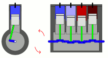
Straight engines
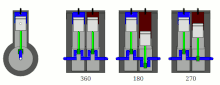
Straight-twin engine with different crankshaft angles
360° crankshaft: This configuration creates the highest levels of primary and secondary imbalance, equivalent to that of a single cylinder engine.;[4] but the even firing order provides smoother power delivery (albeit without the overlapping power strokes of engines with more than four cylinders).
180° crankshaft: This configuration has primary balance but an uneven firing order and a rocking couple;[5] also, the secondary imbalances are half as strong (and at twice the frequency) compared with a 360° straight-twin engine.
270° crankshaft: This configuration minimises secondary imbalances; however, a primary-rotating-plane imbalance is present and the firing order is uneven. The exhaust note and power delivery resemble those of a 90° V-twin engine.
Straight-three engines most commonly use a 120° crankshaft design and have the following characteristics:
Firing interval is perfectly regular (although the power strokes are not overlapping).
Primary and secondary reciprocating-plane balance is perfect.
Primary and secondary rotating-plane imbalances are present.
Straight-four engines (also called inline-four engines) typically use an up–down–down–up 180° crankshaft design and have the following characteristics:
Firing interval is perfectly regular (although the power strokes are not overlapping).
Primary and secondary reciprocating-plane imbalances are present.
Secondary reciprocating forces are high, due to all four pistons being in phase at twice the rotating frequency.
Counterweights have been used on passenger car engines since the mid-1930s,[6] either as full counterweight or semi-counterweight (also known as half-counterweight) designs.
Straight-five engines typically use a 72° crankshaft design and have the following characteristics:
A perfectly regular firing interval with overlapping power strokes, resulting in a smoother idle than engines with fewer cylinders.
Primary and secondary reciprocating-plane balance is perfect.
Primary and secondary rotating-plane imbalances are present.
Straight-six engines typically use a 120° crankshaft design, a firing order of 1–5–3–6–2–4 cylinders and have the following characteristics:
A perfectly regular firing interval with overlapping power strokes. The use of two simple three-into-one exhaust manifolds can provide uniform scavenging, since the engine is effectively behaving like two separate straight-three engines in this regard.
Primary and secondary reciprocating-plane balance is perfect.
Primary and secondary rotating-plane balance is perfect.
With a V angle of 90 degrees and offset crank pins, a V-twin engine can have perfect primary balance.
If a shared crank pin is used (such as in a Ducati V-twin engine), the 360° crankshaft results in an uneven firing interval. These engines also have primary reciprocating-plane and rotating-plane imbalances. Where the connecting rods are at different locations along the crankshaft (which is the case unless fork-and-blade connecting rods are used), this offset creates a rocking couple within the engine.
V4 engines come in many different configurations in terms of the 'V' angle and crankshaft configurations. Some examples are:
The Lancia Fulvia V4 engines with narrow V angle have crank pin offsets corresponding to the V angles, so the firing interval matches that of a straight-four engine.
Some V4 engines have irregular firing spacing, and each design needs to be considered separately in terms of all the balancing items. The Honda RC36 engine has a 90° V angle and a 180° crankshaft with firing intervals of 180°–270°–180°–90°, which results in uneven firing intervals within 360 degrees and within 720 degrees of crankshaft rotation. On the other hand, the Honda VFR1200F engine has a 76° V angle and a 360° crankshaft with shared crank pins that have a 28° offset, resulting in 256°–104°–256°–104° firing interval. This engine also has an unusual connecting rod orientation of front–rear–rear–front, with a much wider distance between cylinders ('bore spacing') on the front cylinder bank than on the rear, resulting in reduced rocking couples (at the expense of wider engine width).[7]
V6 engines are commonly produced in the following configurations:
60° V angle: This design results in a compact engine size, and the short crankshaft length reduces the torsional vibrations. Rotating plane imbalances. The staggering of the left and right cylinder banks (due to the thickness of the connecting rod and the crank web) makes the reciprocating plane imbalance more difficult to be reduced using crankshaft counterweights.
90° V angle: This design historically derives from chopping two cylinders off a 90° V8 engine, in order to reduce design and construction costs. An early example is the 3.3L (200cuin) and 3.8L (229cuin)Chevrolet 90° V6 engines, which have an 18° offset crankshaft resulting in an uneven firing interval. Newer examples, such as the Honda C engine, use 30° offset crank pins, resulting in an even firing interval. As per V6 engines with 60° V angles, these engines have primary reciprocating plane and rotating plane imbalances, staggered cylinder banks and smaller secondary imbalances.
Flat engines
BMW R50/2 flat-twin engine viewed from above, showing the offset between the left & right cylinders
[Precision: A 'flat' engine is not necessarily a 'boxer' engine. A 'flat' engine may either be a 180-degree V engine or a 'boxer' engine. A 180-degree V engine as used in the Ferrari 512BB has opposed cylinder pairs whose connecting rods use the same crank throw. Contrary to this, in a 'boxer' engine, as applied in BMW motorcycles, each connecting rod has its own crank throw which is positioned 180 degrees from the crank throw of the opposed cylinder.]
Flat-twin engines typically use 180° crankshafts and separate crank throws and have the following characteristics:
Primary and secondary reciprocating plane balance is perfect.
Primary and secondary rotating plane imbalance is present.
Flat-four engines typically use a left–right–right–left crankshaft configuration and have the following characteristics:
Primary imbalances are caused by the rocking couples of the opposing pistons being staggered (offset front to back). The intensity of this rocking couple is less than a straight-four engine, since the pairs of connecting rods swinging up and down move at different centre of gravity heights.
Secondary imbalances are minimal.
Flat six engines typically use a boxer configuration and have the following characteristics:
An evenly spaced firing interval with overlapping power strokes. A simple three-into-one exhaust for each cylinder bank provides uniform scavenging, since the engine is effectively behaving like two separate straight-three engines in this regard.
Primary reciprocating plane and rotating plane imbalances, due to the distance along the crankshaft between opposing cylinders. A flat-six engine would have perfect primary balance if fork-and-blade connecting rods were used.
Secondary imbalances are minimal, because there are no pairs of cylinders moving in phase, and the imbalance is mostly cancelled out by the opposing cylinder.
Torsional imbalances are lower than straight-six engines, due to the shorter length of a flat-six engine.
Steam locomotives
A driving wheel on a steam locomotive showing the crescent-shaped balance weight
This section is an introduction to the balancing of two steam engines connected by driving wheels and axles as assembled in a railway locomotive.
The effects of unbalanced inertias in a locomotive are briefly shown by describing measurements of locomotive motions as well as deflections in steel bridges. These measurements show the need for various balancing methods as well as other design features to reduce vibration amplitudes and damage to the locomotive itself as well as to the rails and bridges. The example locomotive is a simple, non-compound, type with two outside cylinders and valve gear, coupled driving wheels and a separate tender. Only basic balancing is covered with no mention of the effects of different cylinder arrangements, crank angles, etc. since balancing methods for three- and four-cylinder locomotives can be complicated and diverse.[8] Mathematical treatments can be found in 'further reading'. For example, Dalby's "The Balancing of Engines" covers the treatment of unbalanced forces and couples using polygons. Johnson and Fry both use algebraic calculations.
At speed the locomotive will tend to surge fore-and-aft and nose, or sway, from side to side. It will also tend to pitch and rock. This article looks at these motions that originate from unbalanced inertia forces and couples in the two steam engines and their coupled wheels (some similar motions may be caused by irregularities in the track running surface and stiffness). The first two motions are caused by the reciprocating masses and the last two by the oblique action of the con-rods, or piston thrust, on the guide bars.[9]
There are three degrees to which balancing may be pursued. The most basic is static balancing of the off-centre features on a driving wheel, i.e. the crankpin and its attached parts. In addition, balancing a proportion of the reciprocating parts can be done with additional revolving weight. This weight is combined with that required for the off-centre parts on the wheel and this extra weight causes the wheel to be overbalanced resulting in hammer blow. Lastly, because the above balance weights are in the plane of the wheel and not in the plane of the originating unbalance, the wheel/axle assembly is not dynamically balanced. Dynamic balancing on steam locomotives is known as cross-balancing and is two-plane balancing with the second plane being in the opposite wheel.
A tendency to instability will vary with the design of a particular locomotive class. Relevant factors include its weight and length, the way it is supported on springs and equalizers and how the value of an unbalanced moving mass compares to the unsprung mass and total mass of the locomotive. The way the tender is attached to the locomotive can also modify its behaviour. The resilience of the track in terms of the weight of the rail as well as the stiffness of the roadbed can affect the vibration behaviour of the locomotive.
As well as giving poor human ride quality the rough riding incurs maintenance costs for wear and fractures in both locomotive and track components.
Sources of unbalance
NZR K class (K 88) showing drivers (without tender)
All the driving wheels have an out-of-balance which is caused by their off-centre crank pins and attached components. The main driving wheels have the greatest unbalance since they have the biggest crankpin as well as the revolving portion of the main rod. They also have the valve gear eccentric crank and the back end of the eccentric rod. In common with the linked driving wheels they also have their own portion of the side rod weight. The part of the main rod assigned a revolving motion was originally measured by weighing it supported at each end. A more accurate method became necessary which split the revolving and reciprocating parts based on the position of the centre of percussion. This position was measured by swinging the rod as a pendulum.[10] The unbalance in the remaining driving wheels is caused by a crankpin and side rod weight. The side rod weights assigned to each crankpin are measured by suspending the rod on as many scales as there are crankpins or by calculation.
The reciprocating piston–crosshead–main-rod–valve-motion link is unbalanced and causes a fore-and-aft surging. Their 90-degree separation causes a swaying couple.[11]
Measuring the effects of unbalance
The whole locomotive tends to move under the influence of unbalanced inertia forces. The horizontal motions for unbalanced locomotives were quantified by M. Le Chatelier in France, around 1850, by suspending them on ropes from the roof of a building. They were run up to equivalent road speeds of up to 40MPH and the horizontal motion was traced out by a pencil, mounted on the buffer beam. The trace was an elliptical shape formed by the combined action of the fore-and-aft and swaying motions. The shape could be enclosed in a 5⁄8-inch square for one of the unbalanced locomotives and was reduced to a point when weights were added to counter revolving and reciprocating masses.[12]
The effect of vertical out-of-balance, or varying wheel load on the rail, was quantified by Professor Robinson in the U.S. in 1895. He measured bridge deflections, or strains, and attributed a 28% increase over the static value to unbalanced drivers.[13]
The residual unbalance in locomotives was assessed in three ways on the Pennsylvania Railroad testing plant. In particular, eight locomotives were tested at the Louisiana Purchase Exposition in 1904. The three measurements were:
The critical speed. This was defined as the speed at which the unbalanced reciprocating parts reversed the pull of the locomotive. At higher speeds this motion was damped by throttling oil flow in dashpots. The critical speed varied from 95 RPM for a Baldwin tandem compound to over 310RPM for a Cole compound Atlantic.
the horizontal motion at the pilot. As an example, the Baldwin compound Atlantic moved about 0.80inch at 65MPH compared with 0.10inch for the Cole compound Atlantic.
A qualitative assessment of the load on the plant supporting wheels. A 0.060-inch diameter wire was run under the wheels. Measuring the deformed wire gave an indication of the vertical load on the wheel. For example, a Cole compound Atlantic showed little variation from a 0.020-inch thickness for all speeds up to 75MPH. In contrast, a Baldwin compound Atlantic at 75MPH showed no deformation, which indicated complete lifting of the wheel, for wheel rotation of 30 degrees with a rapid return impact, over rotation of only 20 degrees, to a no-hammer blow deformation of 0.020inch.[14]
Qualitative assessments may be done on a road trip in terms of the riding qualities in the cab. They may not be a reliable indicator of a requirement for better balance as unrelated factors may cause rough riding, such as stuck wedges, fouled equalizers and slack between the engine and tender. Also the position of an out-of-balance axle relative to the locomotive centre of gravity may determine the extent of motion at the cab. A. H. Fetters related that on a 4–8–2 the effects of 26,000lb dynamic augment under the cg did not show up in the cab but the same augment in any other axle would have.[15]
Static balancing of wheels
Balance weights are installed opposite the parts causing the out-of-balance. The only available plane for these weights is in the wheel itself which results in an out-of-balance couple on the wheel/axle assembly. The wheel is statically balanced only.
Static balancing of reciprocating weight
A proportion of the reciprocating weight is balanced with the addition of an extra revolving weight in the wheel, i.e. still only balanced statically. The overbalance causes what is known as hammer blow or dynamic augment, both terms having the same definition as given in the following references. Hammer blow varies about the static mean, alternately adding to and subtracting from it with each wheel revolution.[16] In the United States it is known as dynamic augment, a vertical force caused by a designer's attempt to balance reciprocating parts by incorporating counterbalance in wheels.[17]
The term hammer blow does not describe what takes place very well since the force varies continuously and only in extreme cases when the wheel lifts from the rail for an instant is there a true blow when it comes back down.[18]
Up until about 1923 American locomotives were balanced for static conditions only with as much as 20,000lb variation in main axle load above and below the mean per revolution from the unbalanced couple.[19] The rough riding and damage led to recommendations for dynamic balancing including defining the proportion of reciprocating weight to be balanced as a proportion of the total locomotive weight, or with Franklin buffer,[20] locomotive plus tender weight.
A different source of varying wheel/rail load, piston thrust, is sometimes incorrectly referred to as hammer blow or dynamic augment although it does not appear in the standard definitions of those terms. It also has a different form per wheel revolution as described later.
As an alternative to adding weights to driving wheels the tender could be attached using a tight coupling that would increase the effective mass and wheelbase of the locomotive. The Prussian State Railways built two-cylinder engines with no reciprocating balance but with a rigid tender coupling.[21] The equivalent coupling for late American locomotives was the friction-damped radial buffer.[22][23]
Dynamic balancing of wheel/axle assembly
The crankpin-and-rods weight on the wheels is in a plane outside the wheel plane location for the static balance weight. Two-plane, or dynamic, balancing is necessary if the out-of-balance couple at speed needs to be balanced. The second plane used is in the opposite wheel.
Two-plane, or dynamic, balancing of a locomotive wheel set is known as cross-balancing.[11] Cross-balancing was not recommended by the American Railway Association until 1931. Up to that time only static balancing was done in America, although builders included cross-balancing for export locomotives when specified. Builders in Europe adopted cross-balancing after Le Chatelier published his theory in 1849.[24]
Determination of acceptable hammer blow
Maximum wheel and axle loads are specified for a particular bridge design so the required fatigue life of steel bridges may be achieved.[25] The axle load will not usually be the sum of the two wheel loads because the line of action of the cross-balancing will be different in each wheel.[26] With the locomotive's static weight known the amount of overbalance which may be put into each wheel to partially balance the reciprocating parts is calculated.[27] Strains measured in a bridge under a passing locomotive also contain a component from piston thrust. This is neglected in the above calculations for allowable overbalance in each wheel. It may need to be taken into account.[28]
Response of wheel to hammer blow
Since the rotating force alternately reduces the wheel load as well as augmenting it every revolution the sustainable tractive effort at the contact patch drops off once per wheel revolution and the wheels may slip.[29] Whether slipping occurs depends on how the hammer blow compares on all the coupled wheels at the same time.
Excessive hammer blow from high slipping speeds was a cause of kinked rails with new North American 4–6–4s and 4–8–4s that followed the 1934 A.A.R. recommendation to balance 40% of the reciprocating weight.[8]
Out-of-balance inertia forces in the wheel can cause different vertical oscillations depending on the track stiffness. Slipping tests done over greased sections of track showed, in one case, slight marking of the rail at a slipping speed of 165mph but on softer track severe rail damage at 105mph.[30]
Piston thrust from connecting rod angularity
The steam engine cross-head sliding surface provides the reaction to the connecting rod force on the crank-pin and varies between zero and a maximum twice during each revolution of the crankshaft.[31]
Unlike hammer blow, which alternately adds and subtracts for each revolution of the wheel, piston thrust only adds to the static mean or subtracts from it, twice per revolution, depending on the direction of motion and whether the locomotive is coasting, or drifting.
In a double-acting steam engine, as used in a railway locomotive, the direction of the vertical thrust on the slide bar is always upwards when running forward. It varies from nothing at the end of stroke to a maximum at half stroke when the angle between the con-rod and crank is greatest.[32] When the crank-pin drives the piston, as when coasting, the piston thrust is downwards. The position of maximum thrust is shown by the increased wear at the middle of the slide bars.[33]
The tendency of the variable force on the upper slide is to lift the machine off its lead springs at half-stroke, and ease it down at the ends of stroke. This causes a pitching, and because the maximum up force is not simultaneous for the two cylinders, it will also tend to roll on the springs.[32]
Similarities with balancing other machinery
The dynamic balancing of locomotive wheels, using the wheels as the balancing planes for out-of-balance existing in other planes, is similar to the dynamic balancing of other rotors such as jet engine compressor/turbine assemblies. Residual out-of-balance in the assembled rotor is corrected by installing balance weights in two planes that are accessible with the engine installed in the aircraft. One plane is at the front of the fan and the other at the last turbine stage.[34]
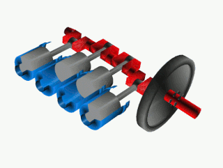
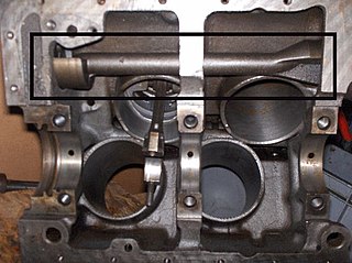
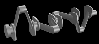
A crankshaft is a mechanical component used in a piston engine to convert the reciprocating motion into rotational motion. The crankshaft is a rotating shaft containing one or more crankpins, that are driven by the pistons via the connecting rods.
A reciprocating engine, also often known as a piston engine, is typically a heat engine that uses one or more reciprocating pistons to convert high temperature and high pressure into a rotating motion. This article describes the common features of all types. The main types are: the internal combustion engine, used extensively in motor vehicles; the steam engine, the mainstay of the Industrial Revolution; and the Stirling engine for niche applications. Internal combustion engines are further classified in two ways: either a spark-ignition (SI) engine, where the spark plug initiates the combustion; or a compression-ignition (CI) engine, where the air within the cylinder is compressed, thus heating it, so that the heated air ignites fuel that is injected then or earlier.
A V6 engine is a six-cylinder piston engine where the cylinders share a common crankshaft and are arranged in a V configuration.
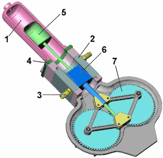
In mechanical engineering, a crosshead is a mechanical joint used as part of the slider-crank linkages of long reciprocating engines and reciprocating compressors to eliminate sideways force on the piston. Also, the crosshead enables the connecting rod to freely move outside the cylinder. Because of the very small bore-to-stroke ratio on such engines, the connecting rod would hit the cylinder walls and block the engine from rotating if the piston was attached directly to the connecting rod like on trunk engines. Therefore, the longitudinal dimension of the crosshead must be matched to the stroke of the engine.
A flat-four engine, also known as a horizontally opposed-four engine or boxer engine, is a four-cylinder piston engine with two banks of cylinders lying on opposite sides of a common crankshaft. The most common type of flat-four engine is the boxer-four engine, each pair of opposed pistons moves inwards and outwards at the same time.
A straight-twin engine, also known as an inline-twin, vertical-twin, or parallel-twin, is a two-cylinder piston engine whose cylinders are arranged in a line along a common crankshaft.
A straight-four engine is a four-cylinder piston engine where cylinders are arranged in a line along a common crankshaft.
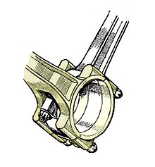
A connecting rod, also called a 'con rod', is the part of a piston engine which connects the piston to the crankshaft. Together with the crank, the connecting rod converts the reciprocating motion of the piston into the rotation of the crankshaft. The connecting rod is required to transmit the compressive and tensile forces from the piston. In its most common form, in an internal combustion engine, it allows pivoting on the piston end and rotation on the shaft end.
Balance shafts are used in piston engines to reduce vibration by cancelling out unbalanced dynamic forces. The counter balance shafts have eccentric weights and rotate in opposite direction to each other, which generates a net vertical force.
Torsional vibration is the angular vibration of an object - commonly a shaft - along its axis of rotation. Torsional vibration is often a concern in power transmission systems using rotating shafts or couplings, where it can cause failures if not controlled. A second effect of torsional vibrations applies to passenger cars. Torsional vibrations can lead to seat vibrations or noise at certain speeds. Both reduce the comfort.
The rhombic drive is a specific method of transferring mechanical energy, or work, used when a single cylinder is used for two separately oscillating pistons.
The crossplane or cross-plane is a crankshaft design for piston engines with a 90° angle between the crank throws. The crossplane crankshaft is the most popular configuration used in V8 road cars.
Reciprocating motion, also called reciprocation, is a repetitive up-and-down or back-and-forth linear motion. It is found in a wide range of mechanisms, including reciprocating engines and pumps. The two opposite motions that comprise a single reciprocation cycle are called strokes.
A crankpin or crank pin, also known as a rod bearing journal, is a mechanical device in an engine which connects the crankshaft to the connecting rod for each cylinder. It has a cylindrical surface, to allow the crankpin to rotate relative to the "big end" of the connecting rod.
A jackshaft is an intermediate shaft used to transfer power from a powered shaft such as the output shaft of an engine or motor to driven shafts such as the drive axles of a locomotive. As applied to railroad locomotives in the 19th and 20th centuries, jackshafts were typically in line with the drive axles of locomotives and connected to them by side rods. In general, each drive axle on a locomotive is free to move about one inch (2.5 cm) vertically relative to the frame, with the locomotive weight carried on springs. This means that if the engine, motor or transmission is rigidly attached to the locomotive frame, it cannot be rigidly connected to the axle. This problem can be solved by mounting the jackshaft on unsprung bearings and using side-rods or chain drives.
In rail terminology, hammer blow or dynamic augment is a vertical force which alternately adds to and subtracts from the locomotive's weight on a wheel. It is transferred to the track by the driving wheels of many steam locomotives. It is an out-of-balance force on the wheel. It is the result of a compromise when a locomotive's wheels are unbalanced to off-set horizontal reciprocating masses, such as connecting rods and pistons, to improve the ride. The hammer blow may cause damage to the locomotive and track if the wheel/rail force is high enough.
In a reciprocating engine, the dead centre is the position of a piston in which it is either farthest from, or nearest to, the crankshaft. The former is known as top dead centre (TDC) while the latter is known as bottom dead centre (BDC).
A big bang engine has an unconventional firing order designed so that some of the power strokes occur simultaneously or in close succession. This is achieved by changing the ignition timing, changing or re-timing the camshaft, and sometimes in combination with a change in crankpin angle. The goal is to change the power delivery characteristics of the engine. A regular firing multi-cylinder engine fires at approximately even intervals, giving a smooth-running engine. Because a big-bang engine has uneven power delivery, they tend to run rougher and generate more vibration than an even-firing engine.
The balancing of rotating bodies is important to avoid vibration. In heavy industrial machines such as gas turbines and electric generators, vibration can cause catastrophic failure, as well as noise and discomfort. In the case of a narrow wheel, balancing simply involves moving the center of gravity to the centre of rotation. For a system to be in complete balance both force and couple polygons should be close in order to prevent the effect of centrifugal force. It is important to design the machine parts wisely so that the unbalance is reduced up to the minimum possible level or eliminated completely.
A return connecting rod, return piston rod or double piston rod engine or back-acting engine is a particular layout for a steam engine.
↑ Proceedings of the American International Association of Railway Superintendents of Bridges and Buildings, p.195
↑ The Pennsylvania Railroad System at the Louisiana Purchase Exposition - Locomotive Tests and Exhibits, The Pennsylvania Railroad Company, 1905, pp.109, 531, 676
↑ Commission, British Transport (1998), Handbook for Railway Steam Locomotive Enginemen, p.92, ISBN0711006288
↑ White, J. L.; Heidari, M. A.; Travis, M. H. (1995), "Experience in Rotor Balancing of Large Commercial Jet Engines", Proceedings of the 13th International Modal Analysis Conference, 2460, Boeing Commercial Airplane Group, fig .3, Bibcode:1995SPIE.2460.1338W
Sources
Swoboda, Bernard (1984), Mécanique des moteurs alternatifs, vol.331 pages, Paris: Editions TECHNIP, ISBN9782710804581
Foale, Tony (2007), Some science of balance(PDF), Tony Foale Designs: Benidoleig, Alicante, Spain, archived(PDF) from the original on 2013-12-27, retrieved 2013-11-04
Taylor, Charles Fayette (1985), The Internal Combustion Engine in Theory and Practice, vol.2: Combustion, Fuels, Materials, Design, Massachusetts: The MIT Press, ISBN0-262-70027-1
Clark, Daniel Kinnear (1855), Railway Machinery, vol.1st ed., Blackie and Son
Johnson, Ralph (2002), The Steam Locomotive, Simmons-Boardman
Fry, Lawford H. (1933), "Locomotive Counterbalancing", Transactions of the American Society of Mechanical Engineers
Dalby, W. E. (1906), The Balancing of Engines, Edward Arnold, Chapter IV – The Balancing of Locomotives
Bevan, Thomas (1945), The theory of Machines, Longmans, Green and Co
This page is based on this Wikipedia article Text is available under the CC BY-SA 4.0 license; additional terms may apply. Images, videos and audio are available under their respective licenses.