Oblique projection

Last updated

Classification of Oblique projection and some 3D projections Comparison of graphical projections.svg
Classification of Oblique projection and some 3D projections

Oblique projection is a simple type of technical drawing of graphical projection used for producing two-dimensional (2D) images of three-dimensional (3D) objects.

Contents

The objects are not in perspective and so do not correspond to any view of an object that can be obtained in practice, but the technique yields somewhat convincing and useful.

Oblique projection is commonly used in technical drawing. The cavalier projection was used by French military artists in the 18th century to depict fortifications.

Oblique projection was used almost universally by Chinese artists from the 1st or 2nd centuries to the 18th century, especially to depict rectilinear objects such as houses. [1]

Various graphical projection techniques can be used in computer graphics, including in Computer Aided Design (CAD), computer games, computer generated animations, and special effects used in movies.

Overview

Comparison of several types of graphical projection. The presence of one or more 90deg angles within a pictorial image is usually a good indication that the perspective is oblique. Graphical projection comparison.png
Comparison of several types of graphical projection. The presence of one or more 90° angles within a pictorial image is usually a good indication that the perspective is oblique.
Various graphical projections and how they are produced Various projections of cube above plane.svg
Various graphical projections and how they are produced
Oblique projection of a cube with foreshortening by half, seen from the side Oblique projection yz.svg
Oblique projection of a cube with foreshortening by half, seen from the side
Top view of a comparison of an oblique projection (left) and an orthographic projection (right) of a unit cube (cyan) onto the projection plane (red). The foreshortening factor (1/2 in this example) is inversely proportional to the tangent of the angle (63.43deg in this example) between the projection plane (colored brown) and the projection lines (dotted). Oblique projection comparison top.svg
Top view of a comparison of an oblique projection (left) and an orthographic projection (right) of a unit cube (cyan) onto the projection plane (red). The foreshortening factor (1/2 in this example) is inversely proportional to the tangent of the angle (63.43° in this example) between the projection plane (colored brown) and the projection lines (dotted).
Front view of the same. Oblique projection comparison front.svg
Front view of the same.

Oblique projection is a type of parallel projection:

In both oblique projection and orthographic projection, parallel lines of the source object produce parallel lines in the projected image. The projectors in oblique projection intersect the projection plane at an oblique angle to produce the projected image, as opposed to the perpendicular angle used in orthographic projection.

Mathematically, the parallel projection of the point on the -plane gives . The constants and uniquely specify a parallel projection. When , the projection is said to be "orthographic" or "orthogonal". Otherwise, it is "oblique". The constants and are not necessarily less than 1, and as a consequence lengths measured on an oblique projection may be either larger or shorter than they were in space. In a general oblique projection, spheres of the space are projected as ellipses on the drawing plane, and not as circles as they would appear from an orthogonal projection.

Oblique drawing is also the crudest "3D" drawing method but the easiest to master. One way to draw using an oblique view is to draw the side of the object you are looking at in two dimensions, i.e. flat, and then draw the other sides at an angle of 45°, but instead of drawing the sides full size they are only drawn with half the depth creating 'forced depth' – adding an element of realism to the object. Even with this 'forced depth', oblique drawings look very unconvincing to the eye. For this reason oblique is rarely used by professional designers or engineers.

Oblique pictorial

In an oblique pictorial drawing, the angles displayed among the axis, as well as the foreshortening factors (scale) are arbitrary. More precisely, any given set of three coplanar segments originating from the same point may be construed as forming some oblique perspective of three sides of a cube. This result is known as Pohlke's theorem, from the German mathematician Pohlke, who published it in the early 19th century. [2]

The resulting distortions make the technique unsuitable for formal, working drawings. Nevertheless, the distortions are partially overcome by aligning one plane of the image parallel to the plane of projection. Doing so creates a true shape image of the chosen plane. This specific category of oblique projections, whereby lengths along the directions and are preserved, but lengths along direction are drawn at angle using a reduction factor is very much in use for industrial drawings.

Cavalier projection

In cavalier projection (sometimes cavalier perspective or high view point) a point of the object is represented by three coordinates, x, y and z. On the drawing, it is represented by only two coordinates, x″ and y″. On the flat drawing, two axes, x and z on the figure, are perpendicular and the length on these axes are drawn with a 1:1 scale; it is thus similar to the dimetric projections, although it is not an axonometric projection, as the third axis, here y, is drawn in diagonal, making an arbitrary angle with the x″ axis, usually 30 or 45°. The length of the third axis is not scaled. [5] [6]

It is very easy to draw, especially with pen and paper. It is thus often used when a figure must be drawn by hand, e.g. on a black board (lesson, oral examination).

The representation was initially used for military fortifications. In French, the "cavalier" (literally rider, horseman, see Cavalry ) is an artificial hill behind the walls that allows sighting of the enemy above the walls. [7] The cavalier perspective was the way the things were seen from this high point. Some also explain the name by the fact that it was the way a rider could see a small object on the ground from his horseback. [8]

Cabinet projection

The term cabinet projection stems from its use in illustrations by the furniture industry. [9] Like cavalier perspective, one face of the projected object is parallel to the viewing plane, and the third axis is projected as going off at an angle (typically atan(2) or about ~63.4°). Unlike cavalier projection, where the third axis keeps its length, with cabinet projection the length of the receding lines is cut in half.

Mathematical formula

As a formula, if the plane facing the viewer is xy, and the receding axis is z, then a point P is projected like this:

Where is the mentioned angle.

The transformation matrix is:

Alternatively one could remove one third from the leading arm projected off the starting face, thus giving the same result.

Military projection

In the military projection, the angles of the x and z-axis and y and z -axis are at 45°, meaning that the angle between the x-axis and the y-axis is 90°. That is, the xy-plane is not skewed. It is rotated over 45°, though. [10]

Examples

Besides technical drawing and illustrations, video games (especially those preceding the advent of 3D games) also often use a form of oblique projection. Examples include SimCity , Ultima VII , Ultima Online , EarthBound , Paperboy and, more recently, Tibia .

See also

Related Research Articles

<span class="mw-page-title-main">Cartesian coordinate system</span> Most common coordinate system (geometry)

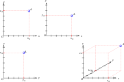
A Cartesian coordinate system in a plane is a coordinate system that specifies each point uniquely by a pair of numerical coordinates, which are the signed distances to the point from two fixed perpendicular oriented lines, measured in the same unit of length. Each reference coordinate line is called a coordinate axis or just axis of the system, and the point where they meet is its origin, at ordered pair (0, 0). The coordinates can also be defined as the positions of the perpendicular projections of the point onto the two axes, expressed as signed distances from the origin.

In electrodynamics, elliptical polarization is the polarization of electromagnetic radiation such that the tip of the electric field vector describes an ellipse in any fixed plane intersecting, and normal to, the direction of propagation. An elliptically polarized wave may be resolved into two linearly polarized waves in phase quadrature, with their polarization planes at right angles to each other. Since the electric field can rotate clockwise or counterclockwise as it propagates, elliptically polarized waves exhibit chirality.

<span class="mw-page-title-main">Gyrocompass</span> Type of non-magnetic compass based on the rotation of the Earth

A gyrocompass is a type of non-magnetic compass which is based on a fast-spinning disc and the rotation of the Earth to find geographical direction automatically. The use of a gyrocompass is one of the seven fundamental ways to determine the heading of a vehicle. A gyroscope is an essential component of a gyrocompass, but they are different devices; a gyrocompass is built to use the effect of gyroscopic precession, which is a distinctive aspect of the general gyroscopic effect. Gyrocompasses are widely used for navigation on ships, because they have two significant advantages over magnetic compasses:

<span class="mw-page-title-main">Angular displacement</span>

Angular displacement of a body is the angle through which a point revolves around a centre or a specified axis in a specified sense. When a body rotates about its axis, the motion cannot simply be analyzed as a particle, as in circular motion it undergoes a changing velocity and acceleration at any time (t). When dealing with the rotation of a body, it becomes simpler to consider the body itself rigid. A body is generally considered rigid when the separations between all the particles remains constant throughout the body's motion, so for example parts of its mass are not flying off. In a realistic sense, all things can be deformable, however this impact is minimal and negligible. Thus the rotation of a rigid body over a fixed axis is referred to as rotational motion.

<span class="mw-page-title-main">Law of sines</span> Property of all triangles on a Euclidean plane

In trigonometry, the law of sines, sine law, sine formula, or sine rule is an equation relating the lengths of the sides of any triangle to the sines of its angles. According to the law,

<span class="mw-page-title-main">Isometric projection</span> Method for visually representing three-dimensional objects

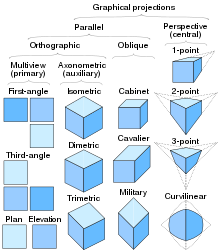
Isometric projection is a method for visually representing three-dimensional objects in two dimensions in technical and engineering drawings. It is an axonometric projection in which the three coordinate axes appear equally foreshortened and the angle between any two of them is 120 degrees.

In mechanics and geometry, the 3D rotation group, often denoted SO(3), is the group of all rotations about the origin of three-dimensional Euclidean space under the operation of composition.

Unit quaternions, known as versors, provide a convenient mathematical notation for representing spatial orientations and rotations of elements in three dimensional space. Specifically, they encode information about an axis-angle rotation about an arbitrary axis. Rotation and orientation quaternions have applications in computer graphics, computer vision, robotics, navigation, molecular dynamics, flight dynamics, orbital mechanics of satellites, and crystallographic texture analysis.

<span class="mw-page-title-main">Orthographic projection</span> Means of projecting three-dimensional objects in two dimensions

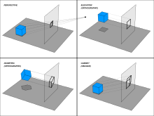
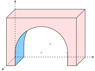
Orthographic projection is a means of representing three-dimensional objects in two dimensions. Orthographic projection is a form of parallel projection in which all the projection lines are orthogonal to the projection plane, resulting in every plane of the scene appearing in affine transformation on the viewing surface. The obverse of an orthographic projection is an oblique projection, which is a parallel projection in which the projection lines are not orthogonal to the projection plane.

<span class="mw-page-title-main">3D projection</span> Design technique

A 3D projection is a design technique used to display a three-dimensional (3D) object on a two-dimensional (2D) surface. These projections rely on visual perspective and aspect analysis to project a complex object for viewing capability on a simpler plane.

A nonholonomic system in physics and mathematics is a physical system whose state depends on the path taken in order to achieve it. Such a system is described by a set of parameters subject to differential constraints and non-linear constraints, such that when the system evolves along a path in its parameter space but finally returns to the original set of parameter values at the start of the path, the system itself may not have returned to its original state. Nonholonomic mechanics is autonomous division of Newtonian mechanics.

<span class="mw-page-title-main">Euler's rotation theorem</span> Movement with a fixed point is rotation

In geometry, Euler's rotation theorem states that, in three-dimensional space, any displacement of a rigid body such that a point on the rigid body remains fixed, is equivalent to a single rotation about some axis that runs through the fixed point. It also means that the composition of two rotations is also a rotation. Therefore the set of rotations has a group structure, known as a rotation group.

In computer graphics, a computer graphics pipeline, rendering pipeline or simply graphics pipeline, is a conceptual model that describes what steps a graphics system needs to perform to render a 3D scene to a 2D screen. Once a 3D model has been created, for instance in a video game or any other 3D computer animation, the graphics pipeline is the process of turning that 3D model into what the computer displays.   Because the steps required for this operation depend on the software and hardware used and the desired display characteristics, there is no universal graphics pipeline suitable for all cases. However, graphics application programming interfaces (APIs) such as Direct3D and OpenGL were created to unify similar steps and to control the graphics pipeline of a given hardware accelerator. These APIs abstract the underlying hardware and keep the programmer away from writing code to manipulate the graphics hardware accelerators.

<span class="mw-page-title-main">Parallel projection</span> Projection of a 3D object onto a plane via parallel rays

In three-dimensional geometry, a parallel projection is a projection of an object in three-dimensional space onto a fixed plane, known as the projection plane or image plane, where the rays, known as lines of sight or projection lines, are parallel to each other. It is a basic tool in descriptive geometry. The projection is called orthographic if the rays are perpendicular (orthogonal) to the image plane, and oblique or skew if they are not.

Gnomonics is the study of the design, construction and use of sundials.

Angular distance is the angle between the two sightlines, or between two point objects as viewed from an observer.

Sinusoidal plane-wave solutions are particular solutions to the electromagnetic wave equation.

Photon polarization is the quantum mechanical description of the classical polarized sinusoidal plane electromagnetic wave. An individual photon can be described as having right or left circular polarization, or a superposition of the two. Equivalently, a photon can be described as having horizontal or vertical linear polarization, or a superposition of the two.

<span class="mw-page-title-main">Axonometry</span> Graphical procedure

Axonometry is a graphical procedure belonging to descriptive geometry that generates a planar image of a three-dimensional object. The term "axonometry" means "to measure along axes", and indicates that the dimensions and scaling of the coordinate axes play a crucial role. The result of an axonometric procedure is a uniformly-scaled parallel projection of the object. In general, the resulting parallel projection is oblique ; but in special cases the result is orthographic, which in this context is called an orthogonal axonometry.

<span class="mw-page-title-main">Courant–Snyder parameters</span> Set of quantities in accelerator physics

In accelerator physics, the Courant–Snyder parameters are a set of quantities used to describe the distribution of positions and velocities of the particles in a beam. When the positions along a single dimension and velocities along that dimension of every particle in a beam are plotted on a phase space diagram, an ellipse enclosing the particles can be given by the equation:

References

  1. Cucker, Felipe (2013). Manifold Mirrors: The Crossing Paths of the Arts and Mathematics. Cambridge University Press. pp. 269–278. ISBN   978-0-521-72876-8.
  2. Weisstein, Eric W. "Pohlke's Theorem". From MathWorld—A Wolfram Web Resource.
  3. 1 2 Parallel Projections Archived 23 April 2007 at the Wayback Machine from PlaneView3D Online
  4. Bolton, William (1995), Basic Engineering, Butterworth-Heinemann GNVQ Engineering Series, BH Newnes, p. 140, ISBN   9780750625845 .
  5. "Repair and Maintenance Manuals - Integrated Publishing". Archived from the original on 22 August 2010. Retrieved 22 August 2010. from "Repair and Maintenance Manuals - Integrated Publishing". Archived from the original on 22 August 2010. Retrieved 22 August 2010.
  6. Ingrid Carlbom, Joseph Paciorek, Planar Geometric Projections and Viewing Transformations, ACM Computing Surveys, v.10 n.4, pp. 465–502, Dec. 1978
  7. Etymologie des maths, letter C (French)
  8. DES QUESTIONS D'ORIGINES (French)
  9. Ching, Francis D. K.; Juroszek, Steven P. (2011), Design Drawing (2nd ed.), John Wiley & Sons, p. 205, ISBN   9781118007372 .
  10. "The Geometry of Perspective Drawing on the Computer" . Retrieved 24 April 2015.

Further reading