
The Nyquist–Shannon sampling theorem is an essential principle for digital signal processing linking the frequency range of a signal and the sample rate required to avoid a type of distortion called aliasing. The theorem states that the sample rate must be at least twice the bandwidth of the signal to avoid aliasing. In practice, it is used to select band-limiting filters to keep aliasing below an acceptable amount when an analog signal is sampled or when sample rates are changed within a digital signal processing function.
A low-pass filter is a filter that passes signals with a frequency lower than a selected cutoff frequency and attenuates signals with frequencies higher than the cutoff frequency. The exact frequency response of the filter depends on the filter design. The filter is sometimes called a high-cut filter, or treble-cut filter in audio applications. A low-pass filter is the complement of a high-pass filter.
The Whittaker–Shannon interpolation formula or sinc interpolation is a method to construct a continuous-time bandlimited function from a sequence of real numbers. The formula dates back to the works of E. Borel in 1898, and E. T. Whittaker in 1915, and was cited from works of J. M. Whittaker in 1935, and in the formulation of the Nyquist–Shannon sampling theorem by Claude Shannon in 1949. It is also commonly called Shannon's interpolation formula and Whittaker's interpolation formula. E. T. Whittaker, who published it in 1915, called it the Cardinal series.

In signal processing and related disciplines, aliasing is the overlapping of frequency components resulting from a sample rate below the Nyquist rate. This overlap results in distortion or artifacts when the signal is reconstructed from samples which causes the reconstructed signal to differ from the original continuous signal. Aliasing that occurs in signals sampled in time, for instance in digital audio or the stroboscopic effect, is referred to as temporal aliasing. Aliasing in spatially sampled signals is referred to as spatial aliasing.

In signal processing, sampling is the reduction of a continuous-time signal to a discrete-time signal. A common example is the conversion of a sound wave to a sequence of "samples". A sample is a value of the signal at a point in time and/or space; this definition differs from the term's usage in statistics, which refers to a set of such values.
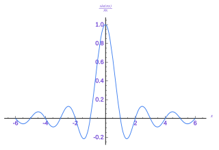
In signal processing, a sinc filter can refer to either a sinc-in-time filter whose impulse response is a sinc function and whose frequency response is rectangular, or to a sinc-in-frequency filter whose impulse response is rectangular and whose frequency response is a sinc function. Calling them according to which domain the filter resembles a sinc avoids confusion. If the domain is unspecified, sinc-in-time is often assumed, or context hopefully can infer the correct domain.

In signal processing, undersampling or bandpass sampling is a technique where one samples a bandpass-filtered signal at a sample rate below its Nyquist rate, but is still able to reconstruct the signal.
Bandlimiting refers to a process which reduces the energy of a signal to an acceptably low level outside of a desired frequency range.
In mathematics, the discrete-time Fourier transform (DTFT) is a form of Fourier analysis that is applicable to a sequence of discrete values.
In digital signal processing, downsampling, compression, and decimation are terms associated with the process of resampling in a multi-rate digital signal processing system. Both downsampling and decimation can be synonymous with compression, or they can describe an entire process of bandwidth reduction (filtering) and sample-rate reduction. When the process is performed on a sequence of samples of a signal or a continuous function, it produces an approximation of the sequence that would have been obtained by sampling the signal at a lower rate.
In signal processing, oversampling is the process of sampling a signal at a sampling frequency significantly higher than the Nyquist rate. Theoretically, a bandwidth-limited signal can be perfectly reconstructed if sampled at the Nyquist rate or above it. The Nyquist rate is defined as twice the bandwidth of the signal. Oversampling is capable of improving resolution and signal-to-noise ratio, and can be helpful in avoiding aliasing and phase distortion by relaxing anti-aliasing filter performance requirements.
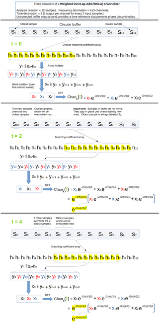
In signal processing, a filter bank is an array of bandpass filters that separates the input signal into multiple components, each one carrying a sub-band of the original signal. One application of a filter bank is a graphic equalizer, which can attenuate the components differently and recombine them into a modified version of the original signal. The process of decomposition performed by the filter bank is called analysis ; the output of analysis is referred to as a subband signal with as many subbands as there are filters in the filter bank. The reconstruction process is called synthesis, meaning reconstitution of a complete signal resulting from the filtering process.
The fast wavelet transform is a mathematical algorithm designed to turn a waveform or signal in the time domain into a sequence of coefficients based on an orthogonal basis of small finite waves, or wavelets. The transform can be easily extended to multidimensional signals, such as images, where the time domain is replaced with the space domain. This algorithm was introduced in 1989 by Stéphane Mallat.
In a mixed-signal system, a reconstruction filter, sometimes called an anti-imaging filter, is used to construct a smooth analog signal from a digital input, as in the case of a digital to analog converter (DAC) or other sampled data output device.

Lanczos filtering and Lanczos resampling are two applications of a mathematical formula. It can be used as a low-pass filter or used to smoothly interpolate the value of a digital signal between its samples. In the latter case, it maps each sample of the given signal to a translated and scaled copy of the Lanczos kernel, which is a sinc function windowed by the central lobe of a second, longer, sinc function. The sum of these translated and scaled kernels is then evaluated at the desired points.
Sample-rate conversion, sampling-frequency conversion or resampling is the process of changing the sampling rate or sampling frequency of a discrete signal to obtain a new discrete representation of the underlying continuous signal. Application areas include image scaling and audio/visual systems, where different sampling rates may be used for engineering, economic, or historical reasons.
The zero-order hold (ZOH) is a mathematical model of the practical signal reconstruction done by a conventional digital-to-analog converter (DAC). That is, it describes the effect of converting a discrete-time signal to a continuous-time signal by holding each sample value for one sample interval. It has several applications in electrical communication.
In rotordynamics, order tracking is a family of signal processing tools aimed at transforming a measured signal from time domain to angular domain. These techniques are applied to asynchronously sampled signals to obtain the same signal sampled at constant angular increments of a reference shaft. In some cases the outcome of the Order Tracking is directly the Fourier transform of such angular domain signal, whose frequency counterpart is defined as "order". Each order represents a fraction of the angular velocity of the reference shaft.
Multidimensional Multirate systems find applications in image compression and coding. Several applications such as conversion between progressive video signals require usage of multidimensional multirate systems. In multidimensional multirate systems, the basic building blocks are decimation matrix (M), expansion matrix(L) and Multidimensional digital filters. The decimation and expansion matrices have dimension of D x D, where D represents the dimension. To extend the one dimensional (1-D) multirate results, there are two different ways which are based on the structure of decimation and expansion matrices. If these matrices are diagonal, separable approaches can be used, which are separable operations in each dimension. Although separable approaches might serve less complexity, non-separable methods, with non-diagonal expansion and decimation matrices, provide much better performance. The difficult part in non-separable methods is to create results in MD case by extend the 1-D case. Polyphase decomposition and maximally decimated reconstruction systems are already carried out.
This article provides a short survey of the concepts, principles and applications of Multirate Filter Banks and Multidimensional Directional Filter Banks.


![Fig 2: The first triangle of the first graph represents the Fourier transform X(f) of a continuous function x(t). The entirety of the first graph depicts the discrete-time Fourier transform of a sequence x[n] formed by sampling the continuous function x(t) at a low-rate of 1/T. The second graph depicts the application of a lowpass filter at a higher data-rate, implemented by inserting zero-valued samples between the original ones. And the third graph is the DTFT of the filter output. The bottom table expresses the maximum filter bandwidth in various frequency units used by filter design tools. Spectral views of zero-fill and interpolation by lowpass filtering.pdf](http://upload.wikimedia.org/wikipedia/commons/thumb/6/6e/Spectral_views_of_zero-fill_and_interpolation_by_lowpass_filtering.pdf/page1-400px-Spectral_views_of_zero-fill_and_interpolation_by_lowpass_filtering.pdf.jpg)


