Schematic diagram of a boiling water reactor (BWR):
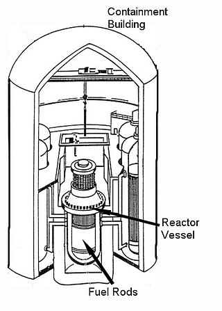
Reactor pressure vessel
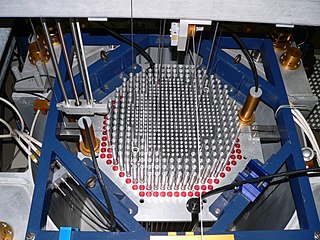
Nuclear fuel element
Control rods
Recirculation pumps
Control rod drives
Steam
Feedwater
High-pressure turbine
Low-pressure turbine
Generator
Exciter
Condenser
Coolant
Pre-heater
Feedwater pump
Cold-water pump
Concrete enclosure
Connection to electricity grid
A boiling water reactor (BWR) is a type of light waternuclear reactor used for the generation of electrical power. It is the second most common type of electricity-generating nuclear reactor after the pressurized water reactor (PWR), which is also a type of light water nuclear reactor.
The main difference between a BWR and PWR is that in a BWR, the reactor core heats water, which turns to steam and then drives a steam turbine. In a PWR, the reactor core heats water, which does not boil. This hot water then exchanges heat with a lower pressure system, which turns water into steam that drives the turbine.
A boiling water reactor uses demineralized water as a coolant and neutron moderator. Heat is produced by nuclear fission in the reactor core, and this causes the cooling water to boil, producing steam. The steam is directly used to drive a turbine, after which it is cooled in a condenser and converted back to liquid water. This water is then returned to the reactor core, completing the loop. The cooling water is maintained at about 75 atm (7.6 MPa, 1000–1100 psi) so that it boils in the core at about 285°C (550°F). In comparison, there is no significant boiling allowed in a pressurized water reactor (PWR) because of the high pressure maintained in its primary loop—approximately 158 atm (16 MPa, 2300 psi). The core damage frequency of the reactor was estimated to be between 10−4 and 10−7 (i.e., one core damage accident per every 10,000 to 10,000,000 reactor years).[1]
Steam exiting the turbine flows into condensers located underneath the low-pressure turbines, where the steam is cooled and returned to the liquid state (condensate). The condensate is then pumped through feedwater heaters that raise its temperature using extraction steam from various turbine stages. Feedwater from the feedwater heaters enters the reactor pressure vessel (RPV) through nozzles high on the vessel, well above the top of the nuclear fuel assemblies (these nuclear fuel assemblies constitute the "core") but below the water level.
The feedwater enters into the downcomer or annulus region and combines with water exiting the moisture separators. The feedwater subcools the saturated water from the moisture separators. This water now flows down the downcomer or annulus region, which is separated from the core by a tall shroud. The water then goes through either jet pumps or internal recirculation pumps that provide additional pumping power (hydraulic head). The water now makes a 180-degree turn and moves up through the lower core plate into the nuclear core, where the fuel elements heat the water. Water exiting the fuel channels at the top guide is saturated with a steam quality of about 15%. Typical core flow may be 45,000,000kg/h (100,000,000lb/h) with 6,500,000kg/h (14,500,000lb/h) steam flow. However, core-average void fraction is a significantly higher fraction (~40%). These sort of values may be found in each plant's publicly available Technical Specifications, Final Safety Analysis Report, or Core Operating Limits Report.
The heating from the core creates a thermal head that assists the recirculation pumps in recirculating the water inside of the RPV. A BWR can be designed with no recirculation pumps and rely entirely on the thermal head to recirculate the water inside of the RPV. The forced recirculation head from the recirculation pumps is very useful in controlling power, however, and allows achieving higher power levels that would not otherwise be possible. The thermal power level is easily varied by simply increasing or decreasing the forced recirculation flow through the recirculation pumps.
The two-phase fluid (water and steam) above the core enters the riser area, which is the upper region contained inside of the shroud. The height of this region may be increased to increase the thermal natural recirculation pumping head. At the top of the riser area is the moisture separator. By swirling the two-phase flow in cyclone separators, the steam is separated and rises upwards towards the steam dryer while the water remains behind and flows horizontally out into the downcomer or annulus region. In the downcomer or annulus region, it combines with the feedwater flow and the cycle repeats.
The saturated steam that rises above the separator is dried by a chevron dryer structure. The "wet" steam goes through a tortuous path where the water droplets are slowed and directed out into the downcomer or annulus region. The "dry" steam then exits the RPV through four main steam lines and goes to the turbine.
Control systems
Reactor power is controlled via two methods: by inserting or withdrawing control rods (control blades) and by changing the water flow through the reactor core.
Positioning (withdrawing or inserting) control rods is the normal method for controlling power when starting up a BWR. As control rods are withdrawn, neutron absorption decreases in the control material and increases in the fuel, so reactor power increases. As control rods are inserted, neutron absorption increases in the control material and decreases in the fuel, so reactor power decreases. Differently from the PWR, in a BWR the control rods (boron carbide plates) are inserted from below to give a more homogeneous distribution of the power: in the upper side the density of the water is lower due to vapour formation, making the neutron moderation less efficient and the fission probability lower. In normal operation, the control rods are only used to keep a homogeneous power distribution in the reactor and to compensate for the consumption of the fuel, while the power is controlled through the water flow (see below).[2] Some early BWRs and the proposed ESBWR (Economic Simplified BWR made by General Electric Hitachi) designs use only natural circulation with control rod positioning to control power from zero to 100% because they do not have reactor recirculation systems.
Changing (increasing or decreasing) the flow of water through the core is the normal and convenient method for controlling power from approximately 30% to 100% reactor power. When operating on the so-called "100% rod line", power may be varied from approximately 30% to 100% of rated power by changing the reactor recirculation system flow by varying the speed of the recirculation pumps or modulating flow control valves. As flow of water through the core is increased, steam bubbles ("voids") are more quickly removed from the core, the amount of liquid water in the core increases, neutron moderation increases, more neutrons are slowed to be absorbed by the fuel, and reactor power increases. As flow of water through the core is decreased, steam voids remain longer in the core, the amount of liquid water in the core decreases, neutron moderation decreases, fewer neutrons are slowed enough to be absorbed by the fuel, and reactor power decreases.[3] Thus the BWR has a negative void coefficient.
Reactor pressure in a BWR is controlled by the main turbine or main steam bypass valves. Unlike a PWR, where the turbine steam demand is set manually by the operators, in a BWR, the turbine valves will modulate to maintain reactor pressure at a setpoint. Under this control mode, the turbine output will automatically follow reactor power changes. When the turbine is offline or trips, the main steam bypass/dump valves will open to direct steam directly to the condenser. These bypass valves will automatically or manually modulate as necessary to maintain reactor pressure and control the reactor's heatup and cooldown rates while steaming is still in progress.
Reactor water level is controlled by the main feedwater system. From about 0.5% power to 100% power, feedwater will automatically control the water level in the reactor. At low power conditions, the feedwater controller acts as a simple PID control by watching reactor water level. At high power conditions, the controller is switched to a "Three-Element" control mode, where the controller looks at the current water level in the reactor, as well as the amount of water going in and the amount of steam leaving the reactor. By using the water injection and steam flow rates, the feed water control system can rapidly anticipate water level deviations and respond to maintain water level within a few inches of set point. If one of the two feedwater pumps fails during operation, the feedwater system will command the recirculation system to rapidly reduce core flow, effectively reducing reactor power from 100% to 50% in a few seconds. At this power level a single feedwater pump can maintain the core water level. If all feedwater is lost, the reactor will scram and the Emergency Core Cooling System is used to restore reactor water level.
Steam turbines
Steam produced in the reactor core passes through steam separators and dryer plates above the core and then directly to the turbine, which is part of the reactor circuit. Because the water around the core of a reactor is always contaminated with traces of radionuclides due to neutron capture from the water, the turbine must be shielded during normal operation, and radiological protection must be provided during maintenance. The increased cost related to operation and maintenance of a BWR tends to balance the savings due to the simpler design and greater thermal efficiency of a BWR when compared with a PWR. Most of the radioactivity in the water is very short-lived (mostly N-16, with a 7-second half-life), so the turbine hall can be entered soon after the reactor is shut down.
BWR steam turbines employ a high-pressure turbine designed to handle saturated steam, and multiple low-pressure turbines. The high-pressure turbine receives steam directly from the reactor. The high-pressure turbine exhaust passes through a steam reheater which superheats the steam to over 400 degrees F for the low-pressure turbines to use. The exhaust of the low-pressure turbines is sent to the main condenser. The steam reheaters take some of the turbine's steam and use it as a heating source to reheat what comes out of the high-pressure turbine exhaust. While the reheaters take steam away from the turbine, the net result is that the reheaters improve the thermodynamic efficiency of the plant.
A modern BWR fuel assembly comprises 74 to 100 fuel rods, and there are up to approximately 800 assemblies in a reactor core, holding up to approximately 140 short tons of low-enriched uranium. The number of fuel assemblies in a specific reactor is based on considerations of desired reactor power output, reactor core size and reactor power density.
A modern reactor has many safety systems that are designed with a defence in depth philosophy, which is a design philosophy that is integrated throughout construction and commissioning.
A BWR is similar to a pressurized water reactor (PWR) in that the reactor will continue to produce heat even after the fission reactions have stopped, which could make a core damage incident possible. This heat is produced by the radioactive decay of fission products and materials that have been activated by neutron absorption. BWRs contain multiple safety systems for cooling the core after emergency shut down.
Refueling systems
The reactor fuel rods are occasionally replaced by moving them from the reactor pressure vessel to the spent fuel pool. A typical fuel cycle lasts 18–24 months, with about one third of fuel assemblies being replaced during a refueling outage. The remaining fuel assemblies are shuffled to new core locations to maximize the efficiency and power produced in the next fuel cycle.
Because they are hot both radioactively and thermally, this is done via cranes and under water. For this reason the spent fuel storage pools are above the reactor in typical installations. They are shielded by water several times their height, and stored in rigid arrays in which their geometry is controlled to avoid criticality. In the Fukushima Daiichi nuclear disaster this became problematic because water was lost (as it was heated by the spent fuel) from one or more spent fuel pools and the earthquake could have altered the geometry. The fact that the fuel rods' cladding is a zirconium alloy was also problematic since this element can react with steam at temperatures above 1,500K (1,230°C) to produce hydrogen,[4][5] which can ignite with oxygen in the air. Normally the fuel rods are kept sufficiently cool in the reactor and spent fuel pools that this is not a concern, and the cladding remains intact for the life of the rod.
Evolution
Early concepts
The BWR concept was developed slightly later than the PWR concept. Development of the BWR started in the early 1950s, and was a collaboration between General Electric (GE) and several US national laboratories.
Research into nuclear power in the US was led by the three military services. The Navy, seeing the possibility of turning submarines into full-time underwater vehicles, and ships that could steam around the world without refueling, sent their man in engineering, CaptainHyman Rickover to run their nuclear power program. Rickover decided on the PWR route for the Navy, as the early researchers in the field of nuclear power feared that the direct production of steam within a reactor would cause instability, while they knew that the use of pressurized water would definitively work as a means of heat transfer. This concern led to the US's first research effort in nuclear power being devoted to the PWR, which was highly suited for naval vessels (submarines, especially), as space was at a premium, and PWRs could be made compact and high-power enough to fit into such vessels.
But other researchers wanted to investigate whether the supposed instability caused by boiling water in a reactor core would really cause instability. During early reactor development, a small group of engineers accidentally increased the reactor power level on an experimental reactor to such an extent that the water quickly boiled. This shut down the reactor, indicating the useful self-moderating property in emergency circumstances. In particular, Samuel Untermyer II, a researcher at Argonne National Laboratory, proposed and oversaw a series of experiments: the BORAX experiments—to see if a boiling water reactor would be feasible for use in energy production. He found that it was, after subjecting his reactors to quite strenuous tests, proving the safety principles of the BWR.[6]
Following this series of tests, GE got involved and collaborated with Argonne National Laboratory[7] to bring this technology to market. Larger-scale tests were conducted through the late 1950s/early/mid-1960s that only partially used directly generated (primary) nuclear boiler system steam to feed the turbine and incorporated heat exchangers for the generation of secondary steam to drive separate parts of the turbines. The literature does not indicate why this was the case, but it was eliminated on production models of the BWR.
First series of production
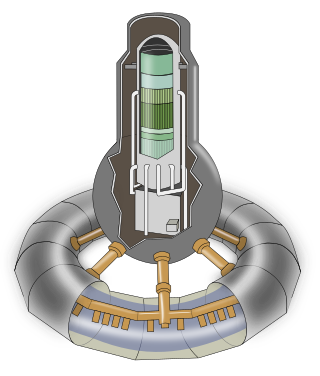
Cross-section sketch of a typical BWR Mark I containment
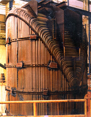
Browns Ferry Unit 1 drywell and wetwell under construction, a BWR/4 using the Mark I containment. In the foreground is the lid of the drywell or primary containment vessel (PCV).
The first generation of production boiling water reactors saw the incremental development of the unique and distinctive features of the BWR: the torus (used to quench steam in the event of a transient requiring the quenching of steam), as well as the drywell, the elimination of the heat exchanger, the steam dryer, the distinctive general layout of the reactor building, and the standardization of reactor control and safety systems. The first, General Electric (GE), series of production BWRs evolved through 6 iterative design phases, each termed BWR/1 through BWR/6. (BWR/4s, BWR/5s, and BWR/6s are the most common types in service today.) The vast majority of BWRs in service throughout the world belong to one of these design phases.
1st generation BWR: BWR/1 with Mark I containment.
2nd generation BWRs: BWR/2, BWR/3 and some BWR/4 with Mark I containment. Other BWR/4, and BWR/5 with Mark-II containment.
3rd generation BWRs: BWR/6 with Mark-III containment.
Containment variants were constructed using either concrete or steel for the Primary Containment, Drywell and Wetwell in various combinations.[8]
Apart from the GE designs there were others by ABB (Asea-Atom), MITSU, Toshiba and KWU (Kraftwerk Union). See List of boiling water reactors.
Advanced boiling water reactor
Cross section of UK ABWR design Reinforced Concrete Containment Vessel
A newer design of BWR is known as the advanced boiling water reactor (ABWR). The ABWR was developed in the late 1980s and early 1990s, and has been further improved to the present day. The ABWR incorporates advanced technologies in the design, including computer control, plant automation, control rod removal, motion, and insertion, in-core pumping, and nuclear safety to deliver improvements over the original series of production BWRs, with a high power output (1350MWe per reactor), and a significantly lowered probability of core damage. Most significantly, the ABWR was a completely standardized design, that could be made for series production.[9]
The ABWR was approved by the United States Nuclear Regulatory Commission for production as a standardized design in the early 1990s. Subsequently, numerous ABWRs were built in Japan. One development spurred by the success of the ABWR in Japan is that General Electric's nuclear energy division merged with Hitachi Corporation's nuclear energy division, forming GE Hitachi Nuclear Energy, which is now the major worldwide developer of the BWR design.
Simplified boiling water reactor - never licensed
Parallel to the development of the ABWR, General Electric also developed a different concept, known as the simplified boiling water reactor (SBWR). This smaller 600 megawatt electrical reactor was notable for its incorporation—for the first time ever in a light water reactor[citation needed]—of "passive safety" design principles. The concept of passive safety means that the reactor, rather than requiring the intervention of active systems, such as emergency injection pumps, to keep the reactor within safety margins, was instead designed to return to a safe state solely through operation of natural forces if a safety-related contingency developed.
For example, if the reactor got too hot, it would trigger a system that would release soluble neutron absorbers (generally a solution of borated materials, or a solution of borax), or materials that greatly hamper a chain reaction by absorbing neutrons, into the reactor core. The tank containing the soluble neutron absorbers would be located above the reactor, and the absorption solution, once the system was triggered, would flow into the core through force of gravity, and bring the reaction to a near-complete stop. Another example was the Isolation Condenser system, which relied on the principle of hot water/steam rising to bring hot coolant into large heat exchangers located above the reactor in very deep tanks of water, thus accomplishing residual heat removal. Yet another example was the omission of recirculation pumps within the core; these pumps were used in other BWR designs to keep cooling water moving; they were expensive, hard to reach to repair, and could occasionally fail; so as to improve reliability, the ABWR incorporated no less than 10 of these recirculation pumps, so that even if several failed, a sufficient number would remain serviceable so that an unscheduled shutdown would not be necessary, and the pumps could be repaired during the next refueling outage. Instead, the designers of the simplified boiling water reactor used thermal analysis to design the reactor core such that natural circulation (cold water falls, hot water rises) would bring water to the center of the core to be boiled.
The ultimate result of the passive safety features of the SBWR would be a reactor that would not require human intervention in the event of a major safety contingency for at least 48 hours following the safety contingency; thence, it would only require periodic refilling of cooling water tanks located completely outside of the reactor, isolated from the cooling system, and designed to remove reactor waste heat through evaporation. The simplified boiling water reactor was submitted[when?] to the United States Nuclear Regulatory Commission, however, it was withdrawn[when?] prior to approval; still, the concept remained intriguing to General Electric's designers, and served as the basis of future developments.[citation needed]
During a period beginning in the late 1990s, GE engineers proposed to combine the features of the advanced boiling water reactor design with the distinctive safety features of the simplified boiling water reactor design, along with scaling up the resulting design to a larger size of 1,600MWe (4,500MWth). This Economic Simplified Boiling Water Reactor (ESBWR) design was submitted to the US Nuclear Regulatory Commission for approval in April 2005, and design certification was granted by the NRC in September 2014.[10]
Reportedly, this design has been advertised as having a core damage probability of only 3×10⁻⁸ core damage events per reactor-year.[citation needed] That is, there would need to be 3 million ESBWRs operating before one would expect a single core-damaging event during their 100-year lifetimes. Earlier designs of the BWR, the BWR/4, had core damage probabilities as high as 1×10⁻⁵ core-damage events per reactor-year.[11] This extraordinarily low CDP for the ESBWR far exceeds the other large LWRs on the market.
Comparison with other types
Advantages of BWR
The reactor vessel and associated components operate at a substantially lower pressure of about 70–75 bars (1,020–1,090psi) compared to about 155 bars (2,250psi) in a PWR.
Pressure vessel is subject to significantly less irradiation compared to a PWR, and so does not become as brittle with age.
Operates at a lower nuclear fuel temperature, largely due to heat transfer by the latent heat of vaporization, as opposed to sensible heat in PWRs.
Fewer large metal and overall components due to a lack of steam generators and a pressurizer vessel, as well as the associated primary circuit pumps. (Older BWRs have external recirculation loops, but even this piping is eliminated in modern BWRs, such as the ABWR.) This also makes BWRs simpler to operate.
Lower risk (probability) of a rupture causing loss of coolant compared to a PWR, and lower risk of core damage should such a rupture occur. This is due to fewer pipes, fewer large-diameter pipes, fewer welds and no steam generator tubes.
NRC assessments of limiting fault potentials indicate if such a fault occurred, the average BWR would be less likely to sustain core damage than the average PWR due to the robustness and redundancy of the Emergency Core Cooling System (ECCS).
Measuring the water level in the pressure vessel is the same for both normal and emergency operations, which results in easy and intuitive assessment of emergency conditions.
Can operate at lower core power density levels using natural circulation without forced flow.
A BWR may be designed to operate using only natural circulation so that recirculation pumps are eliminated. (The new ESBWR design uses natural circulation.)
BWRs do not use boric acid to control fission burn-up to avoid the production of tritium (contamination of the turbines),[2] leading to less possibility of corrosion within the reactor vessel and piping. (Corrosion from boric acid must be carefully monitored in PWRs; it has been demonstrated that reactor vessel head corrosion can occur if the reactor vessel head is not properly maintained. See Davis-Besse. Since BWRs do not utilize boric acid, these contingencies are eliminated.)
The power control by reduction of the moderator density (vapour bubbles in the water) instead of by addition of neutron absorbers (boric acid in PWR) leads to breeding of U-238 by fast neutrons, producing fissile Pu-239.[2]
This effect is amplified in reduced moderation boiling water reactors, resulting in a light water reactor with improved fuel utilization and reduced long-lived radioactive waste more characteristic of sodium breeder reactors.
BWRs generally have N-2 redundancy on their major safety-related systems, which normally consist of four "trains" of components. This generally means that up to two of the four components of a safety system can fail and the system will still perform if called upon.
Due to their single major vendor (GE/Hitachi), the current fleet of BWRs have predictable, uniform designs that, while not completely standardized, generally are very similar to one another. The ABWR/ESBWR designs are completely standardized. Lack of standardization remains a problem with PWRs, as, at least in the United States, there are three design families represented among the current PWR fleet (Combustion Engineering, Westinghouse, and Babcock & Wilcox), and within these families, there are quite divergent designs. Still, some countries could reach a high level of standardisation with PWRs, like France.
Additional families of PWRs are being introduced. For example, Mitsubishi's APWR, Areva's US-EPR, and Westinghouse's AP1000/AP600 will add diversity and complexity to an already diverse crowd, and possibly cause customers seeking stability and predictability to seek other designs, such as the BWR.
BWRs are overrepresented in imports, when the importing nation does not have a nuclear navy (PWRs are favored by nuclear naval states due to their compact, high-power design used on nuclear-powered vessels; since naval reactors are generally not exported, they cause national skill to be developed in PWR design, construction, and operation). This may be due to the fact that BWRs are ideally suited for peaceful uses like power generation, process/industrial/district heating, and desalination, due to low cost, simplicity, and safety focus, which come at the expense of larger size and slightly lower thermal efficiency.
Japan experimented with both PWRs and BWRs, but most builds as of late have been of BWRs, specifically ABWRs.
In the CEGB open competition in the early 1960s for a standard design for UK 2nd-generation power reactors, the PWR didn't even make it to the final round, which was a showdown between the BWR (preferred for its easily understood design as well as for being predictable and "boring") and the AGR, a uniquely British design; the indigenous design won, possibly on technical merits, possibly due to the proximity of a general election.[citation needed] In the 1980s the CEGB built a PWR, Sizewell B.
Disadvantages of BWR
BWRs require more complex calculations for managing consumption of nuclear fuel during operation due to "two-phase (water and steam) fluid flow" in the upper part of the core. This also requires more instrumentation in the reactor core.
Larger reactor pressure vessel than for a PWR of similar power, with correspondingly higher cost, in particular for older models that still use a main steam generator and associated piping.
Contamination of the turbine by short-lived activation products. This means that shielding and access control around the steam turbine are required during normal operations due to the radiation levels arising from the steam entering directly from the reactor core. This is a moderately minor concern, as most of the radiation flux is due to Nitrogen-16 (activation of oxygen in the water), which has a half-life of 7.1 seconds, allowing the turbine chamber to be entered within minutes of shutdown. Extensive experience demonstrates that shutdown maintenance on the turbine, condensate, and feedwater components of a BWR can be performed essentially as a fossil-fuel plant.[citation needed]
Though the current BWRs are considered[1] to be less likely to suffer core damage from the "1 in 100,000 reactor-year" limiting fault than the present fleet of PWRs (due to increased ECCS robustness and redundancy), there have been concerns raised about the pressure containment ability of the as-built, unmodified Mark I containment – that such may be insufficient to contain pressures generated by a limiting fault combined with complete ECCS failure that results in extremely severe core damage. In this double failure scenario, assumed to be extremely unlikely prior to the Fukushima I nuclear accidents, an unmodified Mark I containment can allow some degree of radioactive release to occur. This is supposed to be mitigated by the modification of the Mark I containment; namely, the addition of an outgas stack system that, if containment pressure exceeds critical setpoints, is supposed to allow the orderly discharge of pressurizing gases after the gases pass through activated carbon filters designed to trap radionuclides.[12]
Control rod issues
Control rods are inserted from below for current BWR designs. There are two available hydraulic power sources that can drive the control rods into the core for a BWR under emergency conditions. There is a dedicated high-pressure hydraulic accumulator and also the pressure inside of the reactor pressure vessel available to each control rod. Either the dedicated accumulator (one per rod) or reactor pressure is capable of fully inserting each rod. Most other reactor types use top-entry control rods that are held up in the withdrawn position by electromagnets, causing them to fall into the reactor by gravity if power is lost. This advantage is partially offset by the fact that hydraulic forces provide much greater rod insertion forces than gravity, and as a consequence, BWR control rods are much less likely to jam in a partially inserted position due to damage to the control rod channels in a core damage event. Bottom-entry control rods also permit refueling without removal of the control rods and drives, as well as testing of the control rod systems with an open pressure vessel during refueling.
Technical and background information
This section needs attention from an expert in Physics. The specific problem is: technical section has been alleged by an editor to contain certain factual inaccuracies. See the talk page for details.WikiProject Physics may be able to help recruit an expert.(December 2014)
Start-up ("going critical")
Reactor start up (criticality) is achieved by withdrawing control rods from the core to raise core reactivity to a level where it is evident that the nuclear chain reaction is self-sustaining. This is known as "going critical". Control rod withdrawal is performed slowly, as to carefully monitor core conditions as the reactor approaches criticality. When the reactor is observed to become slightly super-critical, that is, reactor power is increasing on its own, the reactor is declared critical.
Rod motion is performed using rod drive control systems. Newer BWRs such as the ABWR and ESBWR as well as all German and Swedish BWRs use the Fine Motion Control Rod Drive system, which allows multiple rods to be controlled with very smooth motions. This allows a reactor operator to evenly increase the core's reactivity until the reactor is critical. Older BWR designs use a manual control system, which is usually limited to controlling one or four control rods at a time, and only through a series of notched positions with fixed intervals between these positions. Due to the limitations of the manual control system, it is possible while starting-up that the core can be placed into a condition where movement of a single control rod can cause a large nonlinear reactivity change, which could heat fuel elements to the point they fail (melt, ignite, weaken, etc.). As a result, GE developed a set of rules in 1977 called BPWS (Banked Position Withdrawal Sequence) which help minimize the effect of any single control rod movement and prevent fuel damage in the case of a control rod drop accident. BPWS separates control rods into four groups, A1, A2, B1, and B2. Then, either all of the A control rods or B control rods are pulled full out in a defined sequence to create a "checkerboard" pattern. Next, the opposing group (B or A) is pulled in a defined sequence to positions 02, then 04, 08, 16, and finally full out (48). By following a BPWS compliant start-up sequence, the manual control system can be used to evenly and safely raise the entire core to critical, and prevent any fuel rods from exceeding 280 cal/gm energy release during any postulated event which could potentially damage the fuel.[13]
Thermal margins
Several calculated/measured quantities are tracked while operating a BWR:
Maximum Fraction Limiting Critical Power Ratio, or MFLCPR;
Fraction Limiting Linear Heat Generation Rate, or FLLHGR;
Average Planar Linear Heat Generation Rate, or APLHGR;
Pre-Conditioning Interim Operating Management Recommendation, or PCIOMR;
MFLCPR, FLLHGR, and APLHGR must be kept less than 1.0 during normal operation; administrative controls are in place to assure some margin of error and margin of safety to these licensed limits. Typical computer simulations divide the reactor core into 24–25 axialplanes; relevant quantities (margins, burnup, power, void history) are tracked for each "node" in the reactor core (764 fuel assemblies x 25 nodes/assembly = 19100 nodal calculations/quantity).
Maximum fraction limiting critical power ratio (MFLCPR)
Specifically, MFLCPR represents how close the leading fuel bundle is to "dry-out" (or "departure from nucleate boiling" for a PWR). Transition boiling is the unstable transient region where nucleate boiling tends toward film boiling. A water drop dancing on a hot frying pan is an example of film boiling. During film boiling a volume of insulating vapor separates the heated surface from the cooling fluid; this causes the temperature of the heated surface to increase drastically to once again reach equilibrium heat transfer with the cooling fluid. In other words, steam semi-insulates the heated surface and surface temperature rises to allow heat to get to the cooling fluid (through convection and radiative heat transfer). Nuclear fuel could be damaged by film boiling; this would cause the fuel cladding to overheat and fail.
MFLCPR is monitored with an empirical correlation that is formulated by vendors of BWR fuel (GE, Westinghouse, AREVA-NP). The vendors have test rigs where they simulate nuclear heat with resistive heating and determine experimentally what conditions of coolant flow, fuel assembly power, and reactor pressure will be in/out of the transition boiling region for a particular fuel design. In essence, the vendors make a model of the fuel assembly but power it with resistive heaters. These mock fuel assemblies are put into a test stand where data points are taken at specific powers, flows, pressures. Experimental data is conservatively applied to BWR fuel to ensure that the transition to film boiling does not occur during normal or transient operation. Typical SLMCPR/MCPRSL (Safety Limit MCPR) licensing limit for a BWR core is substantiated by a calculation that proves that 99.9% of fuel rods in a BWR core will not enter the transition to film boiling during normal operation or anticipated operational occurrences.[14] Since the BWR is boiling water, and steam does not transfer heat as well as liquid water, MFLCPR typically occurs at the top of a fuel assembly, where steam volume is the highest.
Fraction limiting linear heat generation rate (FLLHGR)
FLLHGR (FDLRX, MFLPD) is a limit on fuel rod power in the reactor core. For new fuel, this limit is typically around 13kW/ft (43kW/m) of fuel rod. This limit ensures that the centerline temperature of the fuel pellets in the rods will not exceed the melting point of the fuel material (uranium/gadolinium oxides) in the event of the worst possible plant transient/scram anticipated to occur. To illustrate the response of LHGR in transient imagine the rapid closure of the valves that admit steam to the turbines at full power. This causes the immediate cessation of steam flow and an immediate rise in BWR pressure. This rise in pressure effectively subcools the reactor coolant instantaneously; the voids (vapor) collapse into solid water. When the voids collapse in the reactor, the fission reaction is encouraged (more thermal neutrons); power increases drastically (120%) until it is terminated by the automatic insertion of the control rods. So, when the reactor is isolated from the turbine rapidly, pressure in the vessel rises rapidly, which collapses the water vapor, which causes a power excursion which is terminated by the Reactor Protection System. If a fuel pin was operating at 13.0kW/ft prior to the transient, the void collapse would cause its power to rise. The FLLHGR limit is in place to ensure that the highest powered fuel rod will not melt if its power was rapidly increased following a pressurization transient. Abiding by the LHGR limit precludes melting of fuel in a pressurization transient.
Average planar linear heat generation rate (APLHGR)
APLHGR, being an average of the Linear Heat Generation Rate (LHGR), a measure of the decay heat present in the fuel bundles, is a margin of safety associated with the potential for fuel failure to occur during a LBLOCA (large-break loss-of-coolant accident – a massive pipe rupture leading to catastrophic loss of coolant pressure within the reactor, considered the most threatening "design basis accident" in probabilistic risk assessment and nuclear safety and security), which is anticipated to lead to the temporary exposure of the core; this core drying-out event is termed core "uncovery", for the core loses its heat-removing cover of coolant, in the case of a BWR, light water. If the core is uncovered for too long, fuel failure can occur; for the purpose of design, fuel failure is assumed to occur when the temperature of the uncovered fuel reaches a critical temperature (1100°C, 2200°F). BWR designs incorporate failsafe protection systems to rapidly cool and make safe the uncovered fuel prior to it reaching this temperature; these failsafe systems are known as the Emergency Core Cooling System. The ECCS is designed to rapidly flood the reactor pressure vessel, spray water on the core itself, and sufficiently cool the reactor fuel in this event. However, like any system, the ECCS has limits, in this case, to its cooling capacity, and there is a possibility that fuel could be designed that produces so much decay heat that the ECCS would be overwhelmed and could not cool it down successfully.
So as to prevent this from happening, it is required that the decay heat stored in the fuel assemblies at any one time does not overwhelm the ECCS. As such, the measure of decay heat generation known as LHGR was developed by GE's engineers, and from this measure, APLHGR is derived. APLHGR is monitored to ensure that the reactor is not operated at an average power level that would defeat the primary containment systems. When a refueled core is licensed to operate, the fuel vendor/licensee simulate events with computer models. Their approach is to simulate worst case events when the reactor is in its most vulnerable state.
APLHGR is commonly pronounced as "Apple Hugger" in the industry.
PCIOMR is a set of rules and limits to prevent cladding damage due to pellet-clad interaction. During the first nuclear heatup, nuclear fuel pellets can crack. The jagged edges of the pellet can rub and interact with the inner cladding wall. During power increases in the fuel pellet, the ceramic fuel material expands faster than the fuel cladding, and the jagged edges of the fuel pellet begin to press into the cladding, potentially causing a perforation. To prevent this from occurring, two corrective actions were taken. The first is the inclusion of a thin barrier layer against the inner walls of the fuel cladding which are resistant to perforation due to pellet-clad interactions, and the second is a set of rules created under PCIOMR.
The PCIOMR rules require initial "conditioning" of new fuel. This means, for the first nuclear heatup of each fuel element, that local bundle power must be ramped very slowly to prevent cracking of the fuel pellets and limit the differences in the rates of thermal expansion of the fuel. PCIOMR rules also limit the maximum local power change (in kW/ft*hr), prevent pulling control rods below the tips of adjacent control rods, and require control rod sequences to be analyzed against core modelling software to prevent pellet-clad interactions. PCIOMR analysis look at local power peaks and xenon transients which could be caused by control rod position changes or rapid power changes to ensure that local power rates never exceed maximum ratings.
List of BWRs
For a list of operational and decommissioned BWRs, see List of BWRs.
Experimental and other types
Experimental and other non-commercial BWRs include:
Areva Kerena (Based on Siemens SWR 1000, Siemens sold its nuclear business to Areva)
Toshiba ABWR (Not related to GE-Hitachi ABWR, Based on Asea (now part of ABB) BWR 90+ design, ABB exited the nuclear business and the design is now owned by Toshiba via a series of mergers and divestment of nuclear business. Asea→ABB→Westinghouse→Toshiba)
↑ Hinds, David; Maslak, Chris (January 2006). "Next-generation nuclear energy: The ESBWR"(PDF). Nuclear News. La Grange Park, Illinois, United States of America: American Nuclear Society. 49 (1): 35–40. ISSN0029-5574. Archived from the original(PDF) on 2010-07-04. Retrieved 2009-04-04.
↑ NEDO-21231, "Banked Position Withdrawal Sequence," January 1977. General Electric Corporation
↑ http://pbadupws.nrc.gov/docs/ML0523/ML052340664.pdf NUREG-0800, (67:234) Chpt 4, Section 4.4, Rev. 1, Thermal and Hydraulic Design, of the Standard Review Plan for the Review of Safety Analysis Reports for Nuclear Power Plants. LWR Edition. (10 page(s), 7/31/1981)
A nuclear reactor is a device used to initiate and control a fission nuclear chain reaction or nuclear fusion reactions. Nuclear reactors are used at nuclear power plants for electricity generation and in nuclear marine propulsion. Heat from nuclear fission is passed to a working fluid, which in turn runs through steam turbines. These either drive a ship's propellers or turn electrical generators' shafts. Nuclear generated steam in principle can be used for industrial process heat or for district heating. Some reactors are used to produce isotopes for medical and industrial use, or for production of weapons-grade plutonium. As of 2022, the International Atomic Energy Agency reports there are 422 nuclear power reactors and 223 nuclear research reactors in operation around the world.
A pressurized water reactor (PWR) is a type of light-water nuclear reactor. PWRs constitute the large majority of the world's nuclear power plants. In a PWR, the primary coolant (water) is pumped under high pressure to the reactor core where it is heated by the energy released by the fission of atoms. The heated, high pressure water then flows to a steam generator, where it transfers its thermal energy to lower pressure water of a secondary system where steam is generated. The steam then drives turbines, which spin an electric generator. In contrast to a boiling water reactor (BWR), pressure in the primary coolant loop prevents the water from boiling within the reactor. All light-water reactors use ordinary water as both coolant and neutron moderator. Most use anywhere from two to four vertically mounted steam generators; VVER reactors use horizontal steam generators.
A nuclear meltdown is a severe nuclear reactor accident that results in core damage from overheating. The term nuclear meltdown is not officially defined by the International Atomic Energy Agency or by the United States Nuclear Regulatory Commission. It has been defined to mean the accidental melting of the core of a nuclear reactor, however, and is in common usage a reference to the core's either complete or partial collapse.
The RBMK is a class of graphite-moderated nuclear power reactor designed and built by the Soviet Union. The name refers to its design where, instead of a large steel pressure vessel surrounding the entire core, the core is surrounded by a cylindrical annular steel tank inside a concrete vault and each fuel assembly is enclosed in an individual 8 cm (inner) diameter pipe. The channels also contain the coolant, and are surrounded by graphite.
Control rods are used in nuclear reactors to control the rate of fission of the nuclear fuel – uranium or plutonium. Their compositions include chemical elements such as boron, cadmium, silver, hafnium, or indium, that are capable of absorbing many neutrons without themselves decaying. These elements have different neutron capture cross sections for neutrons of various energies. Boiling water reactors (BWR), pressurized water reactors (PWR), and heavy-water reactors (HWR) operate with thermal neutrons, while breeder reactors operate with fast neutrons. Each reactor design can use different control rod materials based on the energy spectrum of its neutrons. Control rods have been used in nuclear aircraft engines like Project Pluto as a method of control.
The light-water reactor (LWR) is a type of thermal-neutron reactor that uses normal water, as opposed to heavy water, as both its coolant and neutron moderator; furthermore a solid form of fissile elements is used as fuel. Thermal-neutron reactors are the most common type of nuclear reactor, and light-water reactors are the most common type of thermal-neutron reactor.
Passive nuclear safety is a design approach for safety features, implemented in a nuclear reactor, that does not require any active intervention on the part of the operator or electrical/electronic feedback in order to bring the reactor to a safe shutdown state, in the event of a particular type of emergency. Such design features tend to rely on the engineering of components such that their predicted behaviour would slow down, rather than accelerate the deterioration of the reactor state; they typically take advantage of natural forces or phenomena such as gravity, buoyancy, pressure differences, conduction or natural heat convection to accomplish safety functions without requiring an active power source. Many older common reactor designs use passive safety systems to a limited extent, rather, relying on active safety systems such as diesel-powered motors. Some newer reactor designs feature more passive systems; the motivation being that they are highly reliable and reduce the cost associated with the installation and maintenance of systems that would otherwise require multiple trains of equipment and redundant safety class power supplies in order to achieve the same level of reliability. However, weak driving forces that power many passive safety features can pose significant challenges to effectiveness of a passive system, particularly in the short term following an accident.
A containment building is a reinforced steel, concrete or lead structure enclosing a nuclear reactor. It is designed, in any emergency, to contain the escape of radioactive steam or gas to a maximum pressure in the range of 275 to 550 kPa. The containment is the fourth and final barrier to radioactive release, the first being the fuel ceramic itself, the second being the metal fuel cladding tubes, the third being the reactor vessel and coolant system.
The advanced boiling water reactor (ABWR) is a Generation III boiling water reactor. The ABWR is currently offered by GE Hitachi Nuclear Energy (GEH) and Toshiba. The ABWR generates electrical power by using steam to power a turbine connected to a generator; the steam is boiled from water using heat generated by fission reactions within nuclear fuel. Kashiwazaki-Kariwa unit 6 is considered the first Generation III reactor in the world.
The supercritical water reactor (SCWR) is a concept Generation IV reactor, designed as a light water reactor (LWR) that operates at supercritical pressure. The term critical in this context refers to the critical point of water, and should not be confused with the concept of criticality of the nuclear reactor.
A steam generator is a heat exchanger used to convert water into steam from heat produced in a nuclear reactor core. They are used in pressurized water reactor between the primary and secondary coolant loops.
The water-water energetic reactor (WWER), or VVER is a series of pressurized water reactor designs originally developed in the Soviet Union, and now Russia, by OKB Gidropress. The idea of such a reactor was proposed at the Kurchatov Institute by Savely Moiseevich Feinberg. VVER were originally developed before the 1970s, and have been continually updated. As a result, the name VVER is associated with a wide variety of reactor designs spanning from generation I reactors to modern generation III+ reactor designs. Power output ranges from 70 to 1300 MWe, with designs of up to 1700 MWe in development. The first prototype VVER-210 was built at the Novovoronezh Nuclear Power Plant.
The Economic Simplified Boiling Water Reactor (ESBWR) is a passively safe generation III+ reactor design derived from its predecessor, the Simplified Boiling Water Reactor (SBWR) and from the Advanced Boiling Water Reactor (ABWR). All are designs by GE Hitachi Nuclear Energy (GEH), and are based on previous Boiling Water Reactor designs.
International Reactor Innovative and Secure (IRIS) is a Generation IV reactor design made by an international team of companies, laboratories, and universities and coordinated by Westinghouse. IRIS is hoped to open up new markets for nuclear power and make a bridge from Generation III reactor to Generation IV reactor technology. The design is not yet specific to reactor power output. Notably, a 335 MW output has been proposed, but it could be tweaked to be as low as a 100 MW unit.
The three primary objectives of nuclear reactor safety systems as defined by the U.S. Nuclear Regulatory Commission are to shut down the reactor, maintain it in a shutdown condition and prevent the release of radioactive material.
The B&W mPower was a proposed small modular reactor designed by Babcock & Wilcox, and to be built by Generation mPower LLC, a joint venture of Babcock & Wilcox and Bechtel. It was a Generation III+ integral pressurized water reactor concept.
A nuclear reactor coolant is a coolant in a nuclear reactor used to remove heat from the nuclear reactor core and transfer it to electrical generators and the environment. Frequently, a chain of two coolant loops are used because the primary coolant loop takes on short-term radioactivity from the reactor.
Boiling water reactor safety systems are nuclear safety systems constructed within boiling water reactors in order to prevent or mitigate environmental and health hazards in the event of accident or natural disaster.
General Electric's BWR product line of boiling water reactors represents the designs of a relatively large (~18%) percentage of the commercial fission reactors around the world.
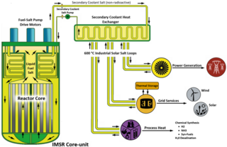
The Integral Molten Salt Reactor (IMSR) is a nuclear power plant design targeted at developing a commercial product for the small modular reactor (SMR) market. It employs molten salt reactor technology which is being developed by the Canadian company Terrestrial Energy. It is based closely on the denatured molten salt reactor (DMSR), a reactor design from Oak Ridge National Laboratory. In addition, it incorporates some elements found in the SmAHTR, a later design from the same laboratory. The IMSR belongs to the DMSR class of molten salt reactors (MSR) and hence is a "burner" reactor that employs a liquid fuel rather than a conventional solid fuel. This liquid contains the nuclear fuel as well as serving as the primary coolant.
This page is based on this Wikipedia article Text is available under the CC BY-SA 4.0 license; additional terms may apply. Images, videos and audio are available under their respective licenses.