Ignition timing

Last updated
Pressure in cylinder pattern in dependence on ignition timing: (a) - misfire, (b) too soon, (c) optimal, (d) too late. Pressure patern in dependence on ignition timing.svg
Pressure in cylinder pattern in dependence on ignition timing: (a) - misfire, (b) too soon, (c) optimal, (d) too late.

In a spark ignition internal combustion engine, ignition timing is the timing, relative to the current piston position and crankshaft angle, of the release of a spark in the combustion chamber near the end of the compression stroke.

Contents

The need for advancing (or retarding) the timing of the spark is because fuel does not completely burn the instant the spark fires. The combustion gases take a period of time to expand and the angular or rotational speed of the engine can lengthen or shorten the time frame in which the burning and expansion should occur. In a vast majority of cases, the angle will be described as a certain angle advanced before top dead center (BTDC). Advancing the spark BTDC means that the spark is energized prior to the point where the combustion chamber reaches its minimum size, since the purpose of the power stroke in the engine is to force the combustion chamber to expand. Sparks occurring after top dead center (ATDC) are usually counter-productive (producing wasted spark, back-fire, engine knock, etc.) unless there is need for a supplemental or continuing spark prior to the exhaust stroke.

Setting the correct ignition timing is crucial in the performance of an engine. Sparks occurring too soon or too late in the engine cycle are often responsible for excessive vibrations and even engine damage. The ignition timing affects many variables including engine longevity, fuel economy, and engine power. Many variables also affect what the "best" timing is. Modern engines that are controlled in real time by an engine control unit use a computer to control the timing throughout the engine's RPM and load range. Older engines that use mechanical distributors rely on inertia (by using rotating weights and springs) and manifold vacuum in order to set the ignition timing throughout the engine's RPM and load range.

Early cars required the driver to adjust timing via controls according to driving conditions, but this is now automated.

There are many factors that influence proper ignition timing for a given engine. These include the timing of the intake valve(s) or fuel injector(s), the type of ignition system used, the type and condition of the spark plugs, the contents and impurities of the fuel, fuel temperature and pressure, engine speed and load, air and engine temperature, turbo boost pressure or intake air pressure, the components used in the ignition system, and the settings of the ignition system components. Usually, any major engine changes or upgrades will require a change to the ignition timing settings of the engine. [1]

Background

The spark ignition system of mechanically controlled gasoline internal combustion engines consist of a mechanical device, known as a distributor, that triggers and distributes ignition spark to each cylinder relative to piston position in crankshaft degrees relative to top dead centre (TDC).

Spark timing, relative to piston position, is based on static (initial or base) timing without mechanical advance. The distributor's centrifugal timing advance mechanism makes the spark occur sooner as engine speed increases. Many of these engines will also use a vacuum advance that advances timing during light loads and deceleration, independent of the centrifugal advance. This typically applies to automotive use; marine gasoline engines generally use a similar system but without vacuum advance.

In mid-1963, Ford offered transistorized ignition on their new 427 FE V8. This system only passed a very low current through the ignition points, using a PNP transistor to perform high-voltage switching of the ignition current, allowing for a higher voltage ignition spark, as well as reducing variations in ignition timing due to arc-wear of the breaker points. Engines so equipped carried special stickers on their valve covers reading “427-T.” AC Delco’s Delcotron Transistor Control Magnetic Pulse Ignition System became optional on a number of General Motors vehicles beginning in 1964. The Delco system eliminated the mechanical points completely, using magnetic flux variation for current switching, virtually eliminating point wear concerns. In 1967, Ferrari and Fiat Dinos came equipped with Magneti Marelli Dinoplex electronic ignition, and all Porsche 911s had electronic ignition beginning with the B-Series 1969 models. In 1972, Chrysler introduced a magnetically-triggered pointless electronic ignition system as standard equipment on some production cars, and included it as standard across the board by 1973.

Electronic control of ignition timing was introduced a few years later in 1975-'76 with the introduction of Chrysler's computer-controlled "Lean-Burn" electronic spark advance system. By 1979 with the Bosch Motronic engine management system, technology had advanced to include simultaneous control of both the ignition timing and fuel delivery. These systems form the basis of modern engine management systems.

Setting the ignition timing

Typical dependency of effective power (Pe) and specific fuel consumption on the ignition timing. The optimal setting (red) exists in every engine regime. Power and consumption on ignition timing.svg
Typical dependency of effective power (Pe) and specific fuel consumption on the ignition timing. The optimal setting (red) exists in every engine regime.
Timing light Timinglight.jpg
Timing light

"Timing advance" refers to the number of degrees before top dead center (BTDC) that the sparkplug will fire to ignite the air-fuel mixture in the combustion chamber before the end of the compression stroke. Retarded timing can be defined as changing the timing so that fuel ignition happens later than the manufacturer's specified time. For example, if the timing specified by the manufacturer was set at 12 degrees BTDC initially and adjusted to 11 degrees BTDC, it would be referred to as retarded. In a classic ignition system with breaker points, the basic timing can be set statically using a test light or dynamically using the timing marks and a timing light.

Timing advance is required because it takes time to burn the air-fuel mixture. Igniting the mixture before the piston reaches TDC will allow the mixture to fully burn soon after the piston reaches TDC. If the mixture is ignited at the correct time, maximum pressure in the cylinder will occur sometime after the piston reaches TDC allowing the ignited mixture to push the piston down the cylinder with the greatest force. Ideally, the time at which the mixture should be fully burnt is about 20 degrees ATDC.[ citation needed ] This will maximize the engine's power producing potential. If the ignition spark occurs at a position that is too advanced relative to piston position, the rapidly combusting mixture can actually push against the piston still moving up in its compression stroke, causing knocking (pinking or pinging) and possible engine damage, this usually occurs at low RPM and is known as pre-ignition or in severe cases detonation. If the spark occurs too retarded relative to the piston position, maximum cylinder pressure will occur after the piston is already too far down in the cylinder on its power stroke. This results in lost power, overheating tendencies, high emissions, and unburned fuel.

The ignition timing will need to become increasingly advanced (relative to TDC) as the engine speed increases so that the air-fuel mixture has the correct amount of time to fully burn. As the engine speed (RPM) increases, the time available to burn the mixture decreases but the burning itself proceeds at the same speed, it needs to be started increasingly earlier to complete in time. Poor volumetric efficiency at higher engine speeds also requires increased advancement of ignition timing. The correct timing advance for a given engine speed will allow for maximum cylinder pressure to be achieved at the correct crankshaft angular position. When setting the timing for an automobile engine, the factory timing setting can usually be found on a sticker in the engine bay.

The ignition timing is also dependent on the load of the engine with more load (larger throttle opening and therefore air:fuel ratio) requiring less advance (the mixture burns faster). Also it is dependent on the temperature of the engine with lower temperature allowing for more advance. The speed with which the mixture burns depends on the type of fuel, the amount of turbulence in the airflow (which is tied to the design the cylinder head and valvetrain system) and on the air-fuel ratio. It is a common myth that burn speed is linked with octane rating.

Dynamometer tuning

Setting the ignition timing while monitoring engine power output with a dynamometer is one way to correctly set the ignition timing. After advancing or retarding the timing, a corresponding change in power output will usually occur. A load type dynamometer is the best way to accomplish this as the engine can be held at a steady speed and load while the timing is adjusted for maximum output.

Using a knock sensor to find the correct timing is one method used to tune an engine. In this method, the timing is advanced until knock occurs. The timing is then retarded one or two degrees and set there. This method is inferior to tuning with a dynamometer since it often leads to ignition timing which is excessively advanced particularly on modern engines which do not require as much advance to deliver peak torque. With excessive advance, the engine will be prone to pinging and detonation when conditions change (fuel quality, temperature, sensor issues, etc). After achieving the desired power characteristics for a given engine load/rpm, the spark plugs should be inspected for signs of engine detonation. If there are any such signs, the ignition timing should be retarded until there are none.

The best way to set ignition timing on a load type dynamometer is to slowly advance the timing until peak torque output is reached. Some engines (particularly turbo or supercharged) will not reach peak torque at a given engine speed before they begin to knock (pinging or minor detonation). In this case, engine timing should be retarded slightly below this timing value (known as the "knock limit"). Engine combustion efficiency and volumetric efficiency will change as ignition timing is varied, which means fuel quantity must also be changed as the ignition is varied. After each change in ignition timing, fuel is adjusted also to deliver peak torque.

Mechanical ignition systems

Mechanical ignition systems use a mechanical spark distributor to distribute a high voltage current to the correct spark plug at the correct time. In order to set an initial timing advance or timing retard for an engine, the engine is allowed to idle and the distributor is adjusted to achieve the best ignition timing for the engine at idle speed. This process is called "setting the base advance". There are two methods of increasing timing advance past the base advance. The advances achieved by these methods are added to the base advance number in order to achieve a total timing advance number.

Mechanical timing advance

Distributor weights Distributor weights.jpg
Distributor weights

An increasing mechanical advancement of the timing takes place with increasing engine speed. This is possible by using the law of inertia. Weights and springs inside the distributor rotate and affect the timing advance according to engine speed by altering the angular position of the timing sensor shaft with respect to the actual engine position. This type of timing advance is also referred to as centrifugal timing advance. The amount of mechanical advance is dependent solely on the speed at which the distributor is rotating. In a 2-stroke engine, this is the same as engine RPM. In a 4-stroke engine, this is half the engine RPM. The relationship between advance in degrees and distributor RPM can be drawn as a simple 2-dimensional graph.

Lighter weights or heavier springs can be used to reduce the timing advance at lower engine RPM. Heavier weights or lighter springs can be used to advance the timing at lower engine RPM. Usually, at some point in the engine's RPM range, these weights contact their travel limits, and the amount of centrifugal ignition advance is then fixed above that rpm.

Vacuum timing advance

The second method used to advance (or retard) the ignition timing is called vacuum timing advance. This method is almost always used in addition to mechanical timing advance. It generally increases fuel economy and driveability, particularly at lean mixtures. It also increases engine life through more complete combustion, leaving less unburned fuel to wash away the cylinder wall lubrication (piston ring wear), and less lubricating oil dilution (bearings, camshaft life, etc.). Vacuum advance works by using a manifold vacuum source to advance the timing at low to mid engine load conditions by rotating the position sensor (contact points, hall effect or optical sensor, reluctor stator, etc.) mounting plate in the distributor with respect to the distributor shaft. Vacuum advance is diminished at wide open throttle (WOT), causing the timing advance to return to the base advance in addition to the mechanical advance.

One source for vacuum advance is a small opening located in the wall of the throttle body or carburetor adjacent to but slightly upstream of the edge of the throttle plate. This is called a ported vacuum. The effect of having the opening here is that there is little or no vacuum at idle, hence little or no advance. Other vehicles use vacuum directly from the intake manifold. This provides full engine vacuum (and hence, full vacuum advance) at idle. Some vacuum advance units have two vacuum connections, one at each side of the actuator membrane, connected to both manifold vacuum and ported vacuum. These units will both advance and retard the ignition timing.

On some vehicles, a temperature sensing switch will apply manifold vacuum to the vacuum advance system when the engine is hot or cold, and ported vacuum at normal operating temperature. This is a version of emissions control; the ported vacuum allowed carburetor adjustments for a leaner idle mixture. At high engine temperature, the increased advance raised engine speed to allow the cooling system to operate more efficiently. At low temperature the advance allowed the enriched warm-up mixture to burn more completely, providing better cold-engine running.

Electrical or mechanical switches may be used to prevent or alter vacuum advance under certain conditions. Early emissions electronics would engage some in relation to oxygen sensor signals or activation of emissions-related equipment. It was also common to prevent some or all of the vacuum advance in certain gears to prevent detonation due to lean-burning engines.

Computer-controlled ignition systems

Newer engines typically use computerized ignition systems. The computer has a timing map (lookup table) with spark advance values for all combinations of engine speed and engine load. The computer will send a signal to the ignition coil at the indicated time in the timing map in order to fire the spark plug. Most computers from original equipment manufacturers (OEM) cannot be modified so changing the timing advance curve is not possible. Overall timing changes are still possible, depending on the engine design. Aftermarket engine control units allow the tuner to make changes to the timing map. This allows the timing to be advanced or retarded based on various engine applications. A knock sensor may be used by the ignition system to allow for fuel quality variation.

Bibliography

See also

Related Research Articles

<span class="mw-page-title-main">Exhaust gas recirculation</span> NOx reduction technique used in gasoline and diesel engines

In internal combustion engines, exhaust gas recirculation (EGR) is a nitrogen oxide (NOx) emissions reduction technique used in petrol/gasoline, diesel engines and some hydrogen engines. EGR works by recirculating a portion of an engine's exhaust gas back to the engine cylinders. The exhaust gas displaces atmospheric air and reduces O2 in the combustion chamber. Reducing the amount of oxygen reduces the amount of fuel that can burn in the cylinder thereby reducing peak in-cylinder temperatures. The actual amount of recirculated exhaust gas varies with the engine operating parameters.

<span class="mw-page-title-main">Four-stroke engine</span> Internal combustion engine type

A four-strokeengine is an internal combustion (IC) engine in which the piston completes four separate strokes while turning the crankshaft. A stroke refers to the full travel of the piston along the cylinder, in either direction. The four separate strokes are termed:

  1. Intake: Also known as induction or suction. This stroke of the piston begins at top dead center (T.D.C.) and ends at bottom dead center (B.D.C.). In this stroke the intake valve must be in the open position while the piston pulls an air-fuel mixture into the cylinder by producing vacuum pressure into the cylinder through its downward motion. The piston is moving down as air is being sucked in by the downward motion against the piston.
  2. Compression: This stroke begins at B.D.C, or just at the end of the suction stroke, and ends at T.D.C. In this stroke the piston compresses the air-fuel mixture in preparation for ignition during the power stroke (below). Both the intake and exhaust valves are closed during this stage.
  3. Combustion: Also known as power or ignition. This is the start of the second revolution of the four stroke cycle. At this point the crankshaft has completed a full 360 degree revolution. While the piston is at T.D.C. the compressed air-fuel mixture is ignited by a spark plug or by heat generated by high compression, forcefully returning the piston to B.D.C. This stroke produces mechanical work from the engine to turn the crankshaft.
  4. Exhaust: Also known as outlet. During the exhaust stroke, the piston, once again, returns from B.D.C. to T.D.C. while the exhaust valve is open. This action expels the spent air-fuel mixture through the exhaust valve.

In spark ignition internal combustion engines, knocking occurs when combustion of some of the air/fuel mixture in the cylinder does not result from propagation of the flame front ignited by the spark plug, but one or more pockets of air/fuel mixture explode outside the envelope of the normal combustion front. The fuel-air charge is meant to be ignited by the spark plug only, and at a precise point in the piston's stroke. Knock occurs when the peak of the combustion process no longer occurs at the optimum moment for the four-stroke cycle. The shock wave creates the characteristic metallic "pinging" sound, and cylinder pressure increases dramatically. Effects of engine knocking range from inconsequential to completely destructive.

An ignition system generates a spark or heats an electrode to a high temperature to ignite a fuel-air mixture in spark ignition internal combustion engines, oil-fired and gas-fired boilers, rocket engines, etc. The widest application for spark ignition internal combustion engines is in petrol (gasoline) road vehicles such as cars and motorcycles.

<span class="mw-page-title-main">Contact breaker</span>

A contact breaker is a type of electrical switch, found in the ignition systems of spark-ignition internal combustion engines. The switch is automatically operated by a cam driven by the engine. The timing of operation of the switch is set so that a spark is produced at the right time to ignite the compressed air/fuel mixture in the cylinder of the engine. A mechanism may be provided to slightly adjust timing to allow for varying load on the engine. Since these contacts operate frequently, they are subject to wear, causing erratic ignition of the engine. More recent engines use electronic means to trigger the spark, which eliminated contact wear and allows computer control of ignition timing.

<span class="mw-page-title-main">Distributor</span> Device in the ignition system of an internal combustion engine

A distributor is an enclosed rotating switch used in spark-ignition internal combustion engines that have mechanically timed ignition. The distributor's main function is to route high voltage current from the ignition coil to the spark plugs in the correct firing order, and for the correct amount of time. Except in magneto systems and many modern computer controlled engines that use crank angle/position sensors, the distributor also houses a mechanical or inductive breaker switch to open and close the ignition coil's primary circuit.

<span class="mw-page-title-main">Aircraft engine controls</span>

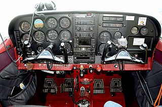
Aircraft engine controls provide a means for the pilot to control and monitor the operation of the aircraft's powerplant. This article describes controls used with a basic internal-combustion engine driving a propeller. Some optional or more advanced configurations are described at the end of the article. Jet turbine engines use different operating principles and have their own sets of controls and sensors.

The Hyundai Beta engines are 1.6 L to 2.0 L I4 built in Ulsan, South Korea.

Lean-burn refers to the burning of fuel with an excess of air in an internal combustion engine. In lean-burn engines the air:fuel ratio may be as lean as 65:1. The air / fuel ratio needed to stoichiometrically combust gasoline, by contrast, is 14.64:1. The excess of air in a lean-burn engine emits far less hydrocarbons. High air–fuel ratios can also be used to reduce losses caused by other engine power management systems such as throttling losses.

<span class="mw-page-title-main">Alfa Romeo Twin Spark engine</span> Motor vehicle engine

Alfa Romeo Twin Spark (TS) technology was used for the first time in the Alfa Romeo Grand Prix car in 1914. In the early 1960s it was used in their race cars to enable it to achieve a higher power output from its engines. And in the early and middle 1980s, Alfa Romeo incorporated this technology into their road cars to enhance their performance and to comply with stricter emission controls.

<span class="mw-page-title-main">MAP sensor</span>

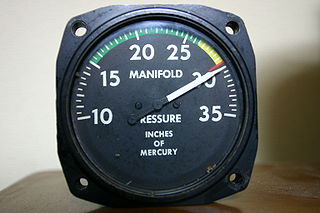
The manifold absolute pressure sensor is one of the sensors used in an internal combustion engine's electronic control system.

<span class="mw-page-title-main">Ignition coil</span> Automobile fuel ignition system component

An ignition coil is an induction coil in an automobile's ignition system that transforms the battery's voltage to the thousands of volts needed to create an electric spark in the spark plugs to ignite the fuel. Some coils have an internal resistor, while others rely on a resistor wire or an external resistor to limit the current flowing into the coil from the car's 12-volt supply. The wire that goes from the ignition coil to the distributor and the high voltage wires that go from the distributor to each of the spark plugs are called spark plug wires or high tension leads. Originally, every ignition coil system required mechanical contact breaker points and a capacitor (condenser). More recent electronic ignition systems use a power transistor to provide pulses to the ignition coil. A modern passenger automobile may use one ignition coil for each engine cylinder, eliminating fault-prone spark plug cables and a distributor to route the high voltage pulses.

Homogeneous Charge Compression Ignition (HCCI) is a form of internal combustion in which well-mixed fuel and oxidizer are compressed to the point of auto-ignition. As in other forms of combustion, this exothermic reaction releases energy that can be transformed in an engine into work and heat.

<span class="mw-page-title-main">Engine control unit</span> Computer that adjusts electronics in an internal combustion propulsion system

An engine control unit (ECU), also commonly called an engine control module (ECM), is a type of electronic control unit that controls a series of actuators on an internal combustion engine to ensure optimal engine performance. It does this by reading values from a multitude of sensors within the engine bay, interpreting the data using multidimensional performance maps, and adjusting the engine actuators. Before ECUs, air–fuel mixture, ignition timing, and idle speed were mechanically set and dynamically controlled by mechanical and pneumatic means.

<span class="mw-page-title-main">Bourke engine</span> Type of internal combustion engine

The Bourke engine was an attempt by Russell Bourke, in the 1920s, to improve the two-stroke internal combustion engine. Despite finishing his design and building several working engines, the onset of World War II, lack of test results, and the poor health of his wife compounded to prevent his engine from ever coming successfully to market. The main claimed virtues of the design are that it has only two moving parts, is lightweight, has two power pulses per revolution, and does not need oil mixed into the fuel.

<span class="mw-page-title-main">Dead centre (engineering)</span> The positions of an engines piston at the top or bottom of its stroke

In a reciprocating engine, the dead centre is the position of a piston in which it is either farthest from, or nearest to, the crankshaft. The former is known as Top Dead Centre (TDC) while the latter is known as Bottom Dead Centre (BDC).

Trionic T5.5 is an engine management system in the Saab Trionic range. It controls ignition, fuel injection and turbo boost pressure. The system was introduced in the 1993 Saab 9000 2.3 Turbo with B234L and B234R engine.

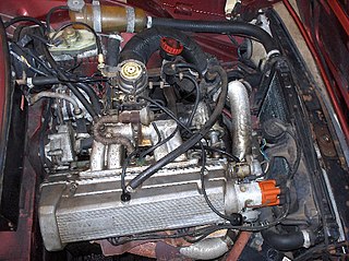
Internal combustion engines come in a wide variety of types, but have certain family resemblances, and thus share many common types of components.

Four-stroking is a condition of two-stroke engines where combustion occurs every four strokes or more, rather than every two. Though normal in some instances at idle, extremely high engine speeds, and when letting off the throttle, such firing is uneven, noisy and may, in cases of malfunction, damage the engine if allowed to continue unabated.

<span class="mw-page-title-main">Internal combustion engine</span> Engine in which the combustion of a fuel occurs with an oxidizer in a combustion chamber

An internal combustion engine is a heat engine in which the combustion of a fuel occurs with an oxidizer in a combustion chamber that is an integral part of the working fluid flow circuit. In an internal combustion engine, the expansion of the high-temperature and high-pressure gases produced by combustion applies direct force to some component of the engine. The force is typically applied to pistons, turbine blades, a rotor, or a nozzle. This force moves the component over a distance, transforming chemical energy into kinetic energy which is used to propel, move or power whatever the engine is attached to. This replaced the external combustion engine for applications where the weight or size of an engine was more important.

References

  1. Julian Edgar. "Getting the Ignition Timing Right".