
An amplifier, electronic amplifier or (informally) amp is an electronic device that can increase the magnitude of a signal. A power amplifier is similarly used to deliver output power, controlled by an input signal. It is a two-port electronic circuit that uses electric power from a power supply to increase the amplitude of a signal applied to its input terminals, producing a proportionally greater amplitude signal at its output. The amount of amplification provided by an amplifier is measured by its gain: the ratio of output voltage, current, or power to input. An amplifier is a circuit that has a power gain greater than one.
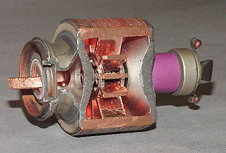
The cavity magnetron is a high-power vacuum tube used in early radar systems and currently in microwave ovens and linear particle accelerators. It generates microwaves using the interaction of a stream of electrons with a magnetic field while moving past a series of cavity resonators, which are small, open cavities in a metal block. Electrons pass by the cavities and cause microwaves to oscillate within, similar to the functioning of a whistle producing a tone when excited by an air stream blown past its opening. The resonant frequency of the arrangement is determined by the cavities' physical dimensions. Unlike other vacuum tubes, such as a klystron or a traveling-wave tube (TWT), the magnetron cannot function as an amplifier for increasing the intensity of an applied microwave signal; the magnetron serves solely as an oscillator, generating a microwave signal from direct current electricity supplied to the vacuum tube.

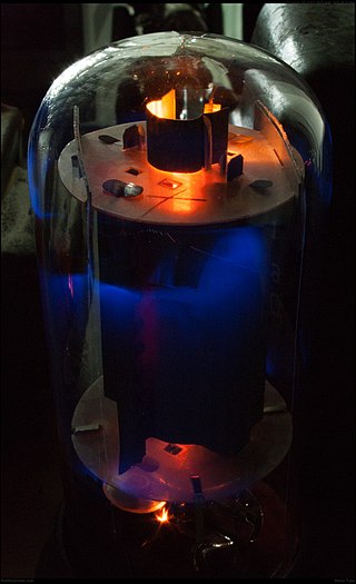
A triode is an electronic amplifying vacuum tube consisting of three electrodes inside an evacuated glass envelope: a heated filament or cathode, a grid, and a plate (anode). Developed from Lee De Forest's 1906 Audion, a partial vacuum tube that added a grid electrode to the thermionic diode, the triode was the first practical electronic amplifier and the ancestor of other types of vacuum tubes such as the tetrode and pentode. Its invention founded the electronics age, making possible amplified radio technology and long-distance telephony. Triodes were widely used in consumer electronics devices such as radios and televisions until the 1970s, when transistors replaced them. Today, their main remaining use is in high-power RF amplifiers in radio transmitters and industrial RF heating devices. In recent years there has been a resurgence in demand for low power triodes due to renewed interest in tube-type audio systems by audiophiles who prefer the pleasantly (warm) distorted sound of tube-based electronics.

A vacuum tube, electron tube, valve, or tube, is a device that controls electric current flow in a high vacuum between electrodes to which an electric potential difference has been applied.
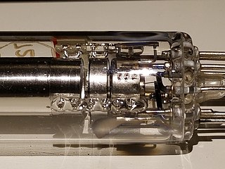
A tetrode is a vacuum tube having four active electrodes. The four electrodes in order from the centre are: a thermionic cathode, first and second grids and a plate. There are several varieties of tetrodes, the most common being the screen-grid tube and the beam tetrode. In screen-grid tubes and beam tetrodes, the first grid is the control grid and the second grid is the screen grid. In other tetrodes one of the grids is a control grid, while the other may have a variety of functions.
A klystron is a specialized linear-beam vacuum tube, invented in 1937 by American electrical engineers Russell and Sigurd Varian, which is used as an amplifier for high radio frequencies, from UHF up into the microwave range. Low-power klystrons are used as oscillators in terrestrial microwave relay communications links, while high-power klystrons are used as output tubes in UHF television transmitters, satellite communication, radar transmitters, and to generate the drive power for modern particle accelerators.

A linear particle accelerator is a type of particle accelerator that accelerates charged subatomic particles or ions to a high speed by subjecting them to a series of oscillating electric potentials along a linear beamline. The principles for such machines were proposed by Gustav Ising in 1924, while the first machine that worked was constructed by Rolf Widerøe in 1928 at the RWTH Aachen University. Linacs have many applications: they generate X-rays and high energy electrons for medicinal purposes in radiation therapy, serve as particle injectors for higher-energy accelerators, and are used directly to achieve the highest kinetic energy for light particles for particle physics.
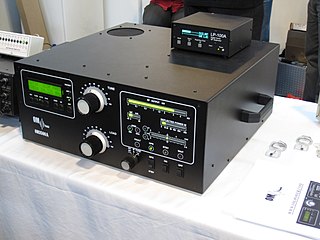
A valve amplifier or tube amplifier is a type of electronic amplifier that uses vacuum tubes to increase the amplitude or power of a signal. Low to medium power valve amplifiers for frequencies below the microwaves were largely replaced by solid state amplifiers in the 1960s and 1970s. Valve amplifiers can be used for applications such as guitar amplifiers, satellite transponders such as DirecTV and GPS, high quality stereo amplifiers, military applications and very high power radio and UHF television transmitters.

A traveling-wave tube or traveling-wave tube amplifier is a specialized vacuum tube that is used in electronics to amplify radio frequency (RF) signals in the microwave range. The TWT belongs to a category of "linear beam" tubes, such as the klystron, in which the radio wave is amplified by absorbing power from a beam of electrons as it passes down the tube. Although there are various types of TWT, two major categories are:
An electron gun is an electrical component in some vacuum tubes that produces a narrow, collimated electron beam that has a precise kinetic energy.

The control grid is an electrode used in amplifying thermionic valves such as the triode, tetrode and pentode, used to control the flow of electrons from the cathode to the anode (plate) electrode. The control grid usually consists of a cylindrical screen or helix of fine wire surrounding the cathode, and is surrounded in turn by the anode. The control grid was invented by Lee De Forest, who in 1906 added a grid to the Fleming valve to create the first amplifying vacuum tube, the Audion (triode).
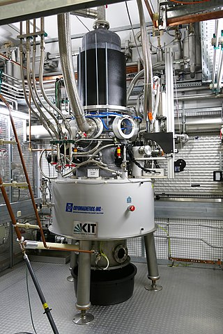
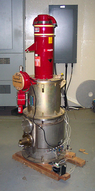
A gyrotron is a class of high-power linear-beam vacuum tubes that generates millimeter-wave electromagnetic waves by the cyclotron resonance of electrons in a strong magnetic field. Output frequencies range from about 20 to 527 GHz, covering wavelengths from microwave to the edge of the terahertz gap. Typical output powers range from tens of kilowatts to 1–2 megawatts. Gyrotrons can be designed for pulsed or continuous operation. The gyrotron was invented by Soviet scientists at NIRFI, based in Nizhny Novgorod, Russia.

A beam tetrode, sometimes called a beam power tube, is a type of vacuum tube or thermionic valve that has two grids and forms the electron stream from the cathode into multiple partially collimated beams to produce a low potential space charge region between the anode and screen grid to return anode secondary emission electrons to the anode when the anode potential is less than that of the screen grid. Beam tetrodes are usually used for power amplification, from audio frequency to radio frequency. The beam tetrode produces greater output power than a triode or pentode with the same anode supply voltage. The first beam tetrode marketed was the Marconi N40, introduced in 1935. Beam tetrodes manufactured and used in the 21st century include the 4CX250B, KT66 and variants of the 6L6.

A pentode is an electronic device having five electrodes. The term most commonly applies to a three-grid amplifying vacuum tube or thermionic valve that was invented by Gilles Holst and Bernhard D.H. Tellegen in 1926. The pentode was developed from the screen-grid tube or shield-grid tube by the addition of a grid between the screen grid and the plate. The screen-grid tube was limited in performance as an amplifier due to secondary emission of electrons from the plate. The additional grid is called the suppressor grid. The suppressor grid is usually operated at or near the potential of the cathode and prevents secondary emission electrons from the plate from reaching the screen grid. The addition of the suppressor grid permits much greater output signal amplitude to be obtained from the plate of the pentode in amplifier operation than from the plate of the screen-grid tube at the same plate supply voltage. Pentodes were widely manufactured and used in electronic equipment until the 1960s to 1970s, during which time transistors replaced tubes in new designs. During the first quarter of the 21st century, a few pentode tubes have been in production for high power radio frequency applications, musical instrument amplifiers, home audio and niche markets.

A crossed-field amplifier (CFA) is a specialized vacuum tube, first introduced in the mid-1950s and frequently used as a microwave amplifier in very-high-power transmitters.

A backward wave oscillator (BWO), also called carcinotron or backward wave tube, is a vacuum tube that is used to generate microwaves up to the terahertz range. Belonging to the traveling-wave tube family, it is an oscillator with a wide electronic tuning range.
A valve RF amplifier or tube amplifier (U.S.) is a device for electrically amplifying the power of an electrical radio frequency signal.

The Barkhausen–Kurz tube, also called the retarding-field tube, reflex triode, B–K oscillator, and Barkhausen oscillator was a high frequency vacuum tube electronic oscillator invented in 1920 by German physicists Heinrich Georg Barkhausen and Karl Kurz. It was the first oscillator that could produce radio power in the ultra-high frequency (UHF) portion of the radio spectrum, above 300 MHz. It was also the first oscillator to exploit electron transit time effects. It was used as a source of high frequency radio waves in research laboratories, and in a few UHF radio transmitters through World War 2. Its output power was low which limited its applications. However it inspired research that led to other more successful transit time tubes such as the klystron, which made the low power Barkhausen-Kurz tube obsolete.

The extended interaction oscillator (EIO) is a linear-beam vacuum tube designed to convert direct current to RF power. The conversion mechanism is the space charge wave process whereby velocity modulation in an electron beam transforms to current or density modulation with distance.
