Neutron generator

Last updated

Nuclear physicist at the Idaho National Laboratory sets up an experiment using an electronic neutron generator. Experiment using an electronic neutron generator.jpg
Nuclear physicist at the Idaho National Laboratory sets up an experiment using an electronic neutron generator.

Neutron generators are neutron source devices which contain compact linear particle accelerators and that produce neutrons by fusing isotopes of hydrogen together. The fusion reactions take place in these devices by accelerating either deuterium, tritium, or a mixture of these two isotopes into a metal hydride target which also contains deuterium, tritium or a mixture of these isotopes. Fusion of deuterium atoms (D + D) results in the formation of a helium-3 ion and a neutron with a kinetic energy of approximately 2.5  MeV. Fusion of a deuterium and a tritium atom (D + T) results in the formation of a helium-4 ion and a neutron with a kinetic energy of approximately 14.1 MeV. Neutron generators have applications in medicine, security, and materials analysis. [1]

Contents

The basic concept was first developed by Ernest Rutherford's team in the Cavendish Laboratory in the early 1930s. Using a linear accelerator driven by a Cockcroft–Walton generator, Mark Oliphant led an experiment that fired deuterium ions into a deuterium-infused metal foil and noticed that a small number of these particles gave off alpha particles. This was the first demonstration of nuclear fusion, as well as the first discovery of Helium-3 and tritium, created in these reactions. The introduction of new power sources has continually shrunk the size of these machines, from Oliphant's that filled the corner of the lab, to modern machines that are highly portable. Thousands of such small, relatively inexpensive systems have been built over the past five decades.

While neutron generators do produce fusion reactions, the number of accelerated ions that cause these reactions is very low. It can be easily demonstrated that the energy released by these reactions is many times lower than the energy needed to accelerate the ions, so there is no possibility of these machines being used to produce net fusion power. A related concept, colliding beam fusion, attempts to address this issue using two accelerators firing at each other.

Neutristor in its simplest form as tested by the inventor at Sandia National Laboratories Neutristor test sample.jpg
Neutristor in its simplest form as tested by the inventor at Sandia National Laboratories

Neutron generator theory and operation

Small neutron generators using the deuterium (D, hydrogen-2, 2H) tritium (T, hydrogen-3, 3H) fusion reactions are the most common accelerator based (as opposed to radioactive isotopes) neutron sources. In these systems, neutrons are produced by creating ions of deuterium, tritium, or deuterium and tritium and accelerating these into a hydride target loaded with deuterium, or deuterium and tritium. The DT reaction is used more than the DD reaction because the yield of the DT reaction is 50–100 times higher than that of the DD reaction.

D + T → n + 4He   En = 14.1 MeV

D + D → n + 3He   En = 2.5 MeV

Neutrons produced by DD and DT reactions are emitted somewhat anisotropically from the target, slightly biased in the forward (in the axis of the ion beam) direction. The anisotropy of the neutron emission from DD and DT reactions arises from the fact the reactions are isotropic in the center of momentum coordinate system (COM) but this isotropy is lost in the transformation from the COM coordinate system to the laboratory frame of reference. In both frames of reference, the He nuclei recoil in the opposite direction to the emitted neutron consistent with the law of conservation of momentum.

The gas pressure in the ion source region of the neutron tubes generally ranges between 0.1 and 0.01  mm Hg. The mean free path of electrons must be shorter than the discharge space to achieve ionization (lower limit for pressure) while the pressure must be kept low enough to avoid formation of discharges at the high extraction voltages applied between the electrodes. The pressure in the accelerating region, however, has to be much lower, as the mean free path of electrons must be longer to prevent formation of a discharge between the high voltage electrodes. [2]

The ion accelerator usually consists of several electrodes with cylindrical symmetry, acting as an einzel lens. The ion beam can thus be focused to a small point at the target. The accelerators typically require power supplies of 100–500 kV. They usually have several stages, with voltage between the stages not exceeding 200 kV to prevent field emission. [2]

In comparison with radionuclide neutron sources, neutron tubes can produce much higher neutron fluxes and consistent (monochromatic) neutron energy spectra can be obtained. The neutron production rate can also be controlled. [2]

Sealed neutron tubes

The central part of a neutron generator is the particle accelerator itself, sometimes called a neutron tube. Neutron tubes have several components including an ion source, ion optic elements, and a beam target; all of these are enclosed within a vacuum-tight enclosure. High voltage insulation between the ion optical elements of the tube is provided by glass and/or ceramic insulators. The neutron tube is, in turn, enclosed in a metal housing, the accelerator head, which is filled with a dielectric medium to insulate the high voltage elements of the tube from the operating area. The accelerator and ion source high voltages are provided by external power supplies. The control console allows the operator to adjust the operating parameters of the neutron tube. The power supplies and control equipment are normally located within 3–10 metres (10–30 ft) of the accelerator head in laboratory instruments, but may be several kilometers away in well logging instruments.

In comparison with their predecessors, sealed neutron tubes do not require vacuum pumps and gas sources for operation. They are therefore more mobile and compact, while also durable and reliable. For example, sealed neutron tubes have replaced radioactive modulated neutron initiators, in supplying a pulse of neutrons to the imploding core of modern nuclear weapons.

Examples of neutron tube ideas date as far back as the 1930s, pre-nuclear weapons era, by German scientists filing a 1938 German patent (March 1938, patent #261,156) and obtaining a United States Patent (July 1941, USP #2,251,190); examples of present state of the art are given by developments such as the Neutristor, [3] a mostly solid state device, resembling a computer chip, invented at Sandia National Laboratories in Albuquerque NM.[ citation needed ] Typical sealed designs are used in a pulsed mode [4] and can be operated at different output levels, depending on the life from the ion source and loaded targets. [5]

Neutristor in an inexpensive vacuum sealed package ready for testing Neutristor in its simplest form.JPG
Neutristor in an inexpensive vacuum sealed package ready for testing

Ion sources

A good ion source should provide a strong ion beam without consuming much of the gas. For hydrogen isotopes, production of atomic ions is favored over molecular ions, as atomic ions have higher neutron yield on collision. The ions generated in the ion source are then extracted by an electric field into the accelerator region, and accelerated towards the target. The gas consumption is chiefly caused by the pressure difference between the ion generating and ion accelerating spaces that has to be maintained. Ion currents of 10 mA at gas consumptions of 40 cm3/hour are achievable. [2]

For a sealed neutron tube, the ideal ion source should use low gas pressure, give high ion current with large proportion of atomic ions, have low gas clean-up, use low power, have high reliability and high lifetime, its construction has to be simple and robust and its maintenance requirements have to be low. [2]

Gas can be efficiently stored in a replenisher, an electrically heated coil of zirconium wire. Its temperature determines the rate of absorption/desorption of hydrogen by the metal, which regulates the pressure in the enclosure.

Cold cathode (Penning)

The Penning source is a low gas pressure, cold cathode ion source which utilizes crossed electric and magnetic fields. The ion source anode is at a positive potential, either dc or pulsed, with respect to the source cathode. The ion source voltage is normally between 2 and 7 kilovolts. A magnetic field, oriented parallel to the source axis, is produced by a permanent magnet. A plasma is formed along the axis of the anode which traps electrons which, in turn, ionize gas in the source. The ions are extracted through the exit cathode. Under normal operation, the ion species produced by the Penning source are over 90% molecular ions. This disadvantage is however compensated for by the other advantages of the system.

One of the cathodes is a cup made of soft iron, enclosing most of the discharge space. The bottom of the cup has a hole through which most of the generated ions are ejected by the magnetic field into the acceleration space. The soft iron shields the acceleration space from the magnetic field, to prevent a breakdown. [2]

Ions emerging from the exit cathode are accelerated through the potential difference between the exit cathode and the accelerator electrode. The schematic indicates that the exit cathode is at ground potential and the target is at high (negative) potential. This is the case in many sealed tube neutron generators. However, in cases when it is desired to deliver the maximum flux to a sample, it is desirable to operate the neutron tube with the target grounded and the source floating at high (positive) potential. The accelerator voltage is normally between 80 and 180 kilovolts.

The accelerating electrode has the shape of a long hollow cylinder. The ion beam has a slightly diverging angle (about 0.1 radian). The electrode shape and distance from target can be chosen so the entire target surface is bombarded with ions. Acceleration voltages of up to 200 kV are achievable.

The ions pass through the accelerating electrode and strike the target. When ions strike the target, 2–3 electrons per ion are produced by secondary emission. In order to prevent these secondary electrons from being accelerated back into the ion source, the accelerator electrode is biased negative with respect to the target. This voltage, called the suppressor voltage, must be at least 500 volts and may be as high as a few kilovolts. Loss of suppressor voltage will result in damage, possibly catastrophic, to the neutron tube.

Some neutron tubes incorporate an intermediate electrode, called the focus or extractor electrode, to control the size of the beam spot on the target. The gas pressure in the source is regulated by heating or cooling the gas reservoir element.

Radio frequency (RF)

Ions can be created by electrons formed in high-frequency electromagnetic field. The discharge is formed in a tube located between electrodes, or inside a coil. Over 90% proportion of atomic ions is achievable. [2]

Targets

The targets used in neutron generators are thin films of metal such as titanium, scandium, or zirconium which are deposited onto a silver, copper or molybdenum substrate. Titanium, scandium, and zirconium form stable chemical compounds called metal hydrides when combined with hydrogen or its isotopes. These metal hydrides are made up of two hydrogen (deuterium or tritium) atoms per metal atom and allow the target to have extremely high densities of hydrogen. This is important to maximize the neutron yield of the neutron tube. The gas reservoir element also uses metal hydrides, e.g. uranium hydride, as the active material.

Titanium is preferred to zirconium as it can withstand higher temperatures (200 °C), and gives higher neutron yield as it captures deuterons better than zirconium. The maximum temperature allowed for the target, above which hydrogen isotopes undergo desorption and escape the material, limits the ion current per surface unit of the target; slightly divergent beams are therefore used. A 1 microampere ion beam accelerated at 200 kV to a titanium-tritium target can generate up to 108 neutrons per second. The neutron yield is mostly determined by the accelerating voltage and the ion current level. [2]

An example of a tritium target in use is a 0.2 mm thick silver disc with a 1 micrometer layer of titanium deposited on its surface; the titanium is then saturated with tritium. [2]

Metals with sufficiently low hydrogen diffusion can be turned into deuterium targets by bombardment of deuterons until the metal is saturated. Gold targets under such condition show four times higher efficiency than titanium. Even better results can be achieved with targets made of a thin film of a high-absorption high-diffusivity metal (e.g. titanium) on a substrate with low hydrogen diffusivity (e.g. silver), as the hydrogen is then concentrated on the top layer and can not diffuse away into the bulk of the material. Using a deuterium-tritium gas mixture, self-replenishing D-T targets can be made. The neutron yield of such targets is lower than of tritium-saturated targets in deuteron beams, but their advantage is much longer lifetime and constant level of neutron production. Self-replenishing targets are also tolerant to high-temperature bake-out of the tubes, as their saturation with hydrogen isotopes is performed after the bakeout and tube sealing. [2]

High voltage power supplies

One approach for generating the high voltage fields needed to accelerate ions in a neutron tube is to use a pyroelectric crystal. In April 2005 researchers at UCLA demonstrated the use of a thermally cycled pyroelectric crystal to generate high electric fields in a neutron generator application. In February 2006 researchers at Rensselaer Polytechnic Institute demonstrated the use of two oppositely poled crystals for this application. Using these low-tech power supplies it is possible to generate a sufficiently high electric field gradient across an accelerating gap to accelerate deuterium ions into a deuterated target to produce the D + D fusion reaction. These devices are similar in their operating principle to conventional sealed-tube neutron generators which typically use Cockcroft–Walton type high voltage power supplies. The novelty of this approach is in the simplicity of the high voltage source. Unfortunately, the relatively low accelerating current that pyroelectric crystals can generate, together with the modest pulsing frequencies that can be achieved (a few cycles per minute) limits their near-term application in comparison with today's commercial products (see below). Also see pyroelectric fusion. [6]

Other technologies

In addition to the conventional neutron generator design described above several other approaches exist to use electrical systems for producing neutrons.

Inertial electrostatic confinement/fusor

Another type of innovative neutron generator is the inertial electrostatic confinement fusion device. This neutron generator avoids using a solid target which will be sputter eroded causing metalization of insulating surfaces. Depletion of the reactant gas within the solid target is also avoided. Far greater operational lifetime is achieved. Originally called a fusor, it was invented by Philo Farnsworth, the inventor of electronic television.

Applications

Neutron generators find application in semiconductor production industry. They also have use cases in the enrichment of depleted uranium, acceleration of breeder reactors, and activation and excitement of experimental thorium reactors.

In material analysis neutron activation analysis is used to determine concentration of different elements in mixed materials such as minerals or ores.

See also

Related Research Articles

<span class="mw-page-title-main">Cathode ray</span> Beam of electrons observed in vacuum tubes

Cathode rays or electron beams (e-beam) are streams of electrons observed in discharge tubes. If an evacuated glass tube is equipped with two electrodes and a voltage is applied, glass behind the positive electrode is observed to glow, due to electrons emitted from the cathode. They were first observed in 1859 by German physicist Julius Plücker and Johann Wilhelm Hittorf, and were named in 1876 by Eugen Goldstein Kathodenstrahlen, or cathode rays. In 1897, British physicist J. J. Thomson showed that cathode rays were composed of a previously unknown negatively charged particle, which was later named the electron. Cathode-ray tubes (CRTs) use a focused beam of electrons deflected by electric or magnetic fields to render an image on a screen.

<span class="mw-page-title-main">Nuclear fusion</span> Process of combining atomic nuclei

Nuclear fusion is a reaction in which two or more atomic nuclei, usually deuterium and tritium, combine to form one or more different atomic nuclei and subatomic particles. The difference in mass between the reactants and products is manifested as either the release or absorption of energy. This difference in mass arises due to the difference in nuclear binding energy between the atomic nuclei before and after the reaction. Nuclear fusion is the process that powers active or main-sequence stars and other high-magnitude stars, where large amounts of energy are released.

<span class="mw-page-title-main">Tritium</span> Isotope of hydrogen with two neutrons

Tritium or hydrogen-3 is a rare and radioactive isotope of hydrogen with a half-life of ~12.3 years. The nucleus of tritium contains one proton and two neutrons, whereas the nucleus of the common isotope hydrogen-1 (protium) contains one proton and zero neutrons, and that of a non-radioactive hydrogen-2 (deuterium) contains one proton and one neutron.

<span class="mw-page-title-main">Fusor</span> An apparatus to create nuclear fusion

A fusor is a device that uses an electric field to heat ions to a temperature in which they undergo nuclear fusion. The machine induces a potential difference between two metal cages, inside a vacuum. Positive ions fall down this voltage drop, building up speed. If they collide in the center, they can fuse. This is one kind of an inertial electrostatic confinement device – a branch of fusion research.

<span class="mw-page-title-main">Van de Graaff generator</span> Electrostatic particle accelerator operating on the triboelectric effect

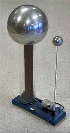
A Van de Graaff generator is an electrostatic generator which uses a moving belt to accumulate electric charge on a hollow metal globe on the top of an insulated column, creating very high electric potentials. It produces very high voltage direct current (DC) electricity at low current levels. It was invented by American physicist Robert J. Van de Graaff in 1929. The potential difference achieved by modern Van de Graaff generators can be as much as 5 megavolts. A tabletop version can produce on the order of 100 kV and can store enough energy to produce visible electric sparks. Small Van de Graaff machines are produced for entertainment, and for physics education to teach electrostatics; larger ones are displayed in some science museums.

<span class="mw-page-title-main">Fusion power</span> Electricity generation through nuclear fusion

Fusion power is a proposed form of power generation that would generate electricity by using heat from nuclear fusion reactions. In a fusion process, two lighter atomic nuclei combine to form a heavier nucleus, while releasing energy. Devices designed to harness this energy are known as fusion reactors. Research into fusion reactors began in the 1940s, but as of 2024, no device has reached net power.

<span class="mw-page-title-main">Neutron source</span> Device that emits neutrons

A neutron source is any device that emits neutrons, irrespective of the mechanism used to produce the neutrons. Neutron sources are used in physics, engineering, medicine, nuclear weapons, petroleum exploration, biology, chemistry, and nuclear power.

<span class="mw-page-title-main">Linear particle accelerator</span> Type of particle accelerator

A linear particle accelerator is a type of particle accelerator that accelerates charged subatomic particles or ions to a high speed by subjecting them to a series of oscillating electric potentials along a linear beamline. The principles for such machines were proposed by Gustav Ising in 1924, while the first machine that worked was constructed by Rolf Widerøe in 1928 at the RWTH Aachen University. Linacs have many applications: they generate X-rays and high energy electrons for medicinal purposes in radiation therapy, serve as particle injectors for higher-energy accelerators, and are used directly to achieve the highest kinetic energy for light particles for particle physics.

Muon-catalyzed fusion is a process allowing nuclear fusion to take place at temperatures significantly lower than the temperatures required for thermonuclear fusion, even at room temperature or lower. It is one of the few known ways of catalyzing nuclear fusion reactions.

<span class="mw-page-title-main">Inertial electrostatic confinement</span> Fusion power research concept

Inertial electrostatic confinement, or IEC, is a class of fusion power devices that use electric fields to confine the plasma rather than the more common approach using magnetic fields found in magnetic confinement fusion (MCF) designs. Most IEC devices directly accelerate their fuel to fusion conditions, thereby avoiding energy losses seen during the longer heating stages of MCF devices. In theory, this makes them more suitable for using alternative aneutronic fusion fuels, which offer a number of major practical benefits and makes IEC devices one of the more widely studied approaches to fusion.

<span class="mw-page-title-main">Gas-filled tube</span> Assembly of electrodes at either end of an insulated tube filled with gas

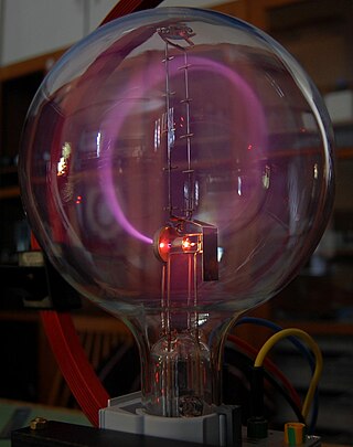
A gas-filled tube, also commonly known as a discharge tube or formerly as a Plücker tube, is an arrangement of electrodes in a gas within an insulating, temperature-resistant envelope. Gas-filled tubes exploit phenomena related to electric discharge in gases, and operate by ionizing the gas with an applied voltage sufficient to cause electrical conduction by the underlying phenomena of the Townsend discharge. A gas-discharge lamp is an electric light using a gas-filled tube; these include fluorescent lamps, metal-halide lamps, sodium-vapor lamps, and neon lights. Specialized gas-filled tubes such as krytrons, thyratrons, and ignitrons are used as switching devices in electric devices.

<span class="mw-page-title-main">Aneutronic fusion</span> Form of fusion power

Aneutronic fusion is any form of fusion power in which very little of the energy released is carried by neutrons. While the lowest-threshold nuclear fusion reactions release up to 80% of their energy in the form of neutrons, aneutronic reactions release energy in the form of charged particles, typically protons or alpha particles. Successful aneutronic fusion would greatly reduce problems associated with neutron radiation such as damaging ionizing radiation, neutron activation, reactor maintenance, and requirements for biological shielding, remote handling and safety.

Pyroelectric fusion refers to the technique of using pyroelectric crystals to generate high strength electrostatic fields to accelerate deuterium ions (tritium might also be used someday) into a metal hydride target also containing deuterium (or tritium) with sufficient kinetic energy to cause these ions to undergo nuclear fusion. It was reported in April 2005 by a team at UCLA. The scientists used a pyroelectric crystal heated from −34 to 7 °C (−29 to 45 °F), combined with a tungsten needle to produce an electric field of about 25 gigavolts per meter to ionize and accelerate deuterium nuclei into an erbium deuteride target. Though the energy of the deuterium ions generated by the crystal has not been directly measured, the authors used 100 keV (a temperature of about 109 K) as an estimate in their modeling. At these energy levels, two deuterium nuclei can fuse to produce a helium-3 nucleus, a 2.45 MeV neutron and bremsstrahlung. Although it makes a useful neutron generator, the apparatus is not intended for power generation since it requires far more energy than it produces.

<span class="mw-page-title-main">Isotopes of hydrogen</span> Hydrogen with different numbers of neutrons

Hydrogen (1H) has three naturally occurring isotopes, sometimes denoted 1
H
, 2
H
, and 3
H
. 1
H
and 2
H
are stable, while 3
H
has a half-life of 12.32(2) years. Heavier isotopes also exist, all of which are synthetic and have a half-life of less than one zeptosecond (10−21 s). Of these, 5
H
is the least stable, while 7
H
is the most.

Neutral-beam injection (NBI) is one method used to heat plasma inside a fusion device consisting in a beam of high-energy neutral particles that can enter the magnetic confinement field. When these neutral particles are ionized by collision with the plasma particles, they are kept in the plasma by the confining magnetic field and can transfer most of their energy by further collisions with the plasma. By tangential injection in the torus, neutral beams also provide momentum to the plasma and current drive, one essential feature for long pulses of burning plasmas. Neutral-beam injection is a flexible and reliable technique, which has been the main heating system on a large variety of fusion devices. To date, all NBI systems were based on positive precursor ion beams. In the 1990s there has been impressive progress in negative ion sources and accelerators with the construction of multi-megawatt negative-ion-based NBI systems at LHD (H0, 180 keV) and JT-60U (D0, 500 keV). The NBI designed for ITER is a substantial challenge (D0, 1 MeV, 40 A) and a prototype is being constructed to optimize its performance in view of the ITER future operations. Other ways to heat plasma for nuclear fusion include RF heating, electron cyclotron resonance heating (ECRH), ion cyclotron resonance heating (ICRH), and lower hybrid resonance heating (LH).

Magnetized Target Fusion (MTF) is a fusion power concept that combines features of magnetic confinement fusion (MCF) and inertial confinement fusion (ICF). Like the magnetic approach, the fusion fuel is confined at lower density by magnetic fields while it is heated into a plasma. As with the inertial approach, fusion is initiated by rapidly squeezing the target to greatly increase fuel density and temperature. Although the resulting density is far lower than in ICF, it is thought that the combination of longer confinement times and better heat retention will let MTF operate, yet be easier to build. The term magneto-inertial fusion (MIF) is similar, but encompasses a wider variety of arrangements. The two terms are often applied interchangeably to experiments.

<span class="mw-page-title-main">Particle accelerator</span> Research apparatus for particle physics

A particle accelerator is a machine that uses electromagnetic fields to propel charged particles to very high speeds and energies, and to contain them in well-defined beams.

<span class="mw-page-title-main">ITER Neutral Beam Test Facility</span>

The ITER Neutral Beam Test Facility is a part of the International Thermonuclear Experimental Reactor (ITER) in Padova, Veneto, Italy. The facility will host the full-scale prototype of the reactor's neutral beam injector, MITICA, and a smaller prototype of its ion source, SPIDER. SPIDER started its operation in June 2018. SPIDER will be used to optimize the ion beam source, to optimize the use of cesium vapor, and to verify the uniformity of the extracted ion beam also during long pulses.

Colliding beam fusion (CBF), or colliding beam fusion reactor (CBFR), is a class of fusion power concepts that are based on two or more intersecting beams of fusion fuel ions that are independently accelerated to fusion energies using a variety of particle accelerator designs or other means. One of the beams may be replaced by a static target, in which case the approach is termed accelerator based fusion or beam-target fusion, but the physics is the same as colliding beams.

Lattice confinement fusion (LCF) is a type of nuclear fusion in which deuteron-saturated metals are exposed to gamma radiation or ion beams, such as in an IEC fusor, avoiding the confined high-temperature gasses used in other methods of fusion.

References

  1. Reijonen, J. "Compact Neutron Generators for Medical, Homeland Security, and Planetary Exploration" (PDF). Proceedings of 2005 Particle Accelerator Conference, Knoxville, Tennessee: 49–53.
  2. 1 2 3 4 5 6 7 8 9 10 van der Horst; H. L. (1964). "VIIIc Neutron Generators" (PDF). Gas-Discharge Tubes. Philips Technical Library. Vol. 16. Eindhoven, Netherlands: Philips Technical Library. pp. 281–295. OCLC   10391645. UDC No. 621.387.
  3. Elizondo-Decanini, J. M.; Schmale, D.; Cich, M.; Martinez, M.; Youngman, K.; Senkow, M.; Kiff, S.; Steele, J.; Goeke, R.; Wroblewski, B.; Desko, J.; Dragt, A. J. (2012). "Novel Surface-Mounted Neutron Generator". IEEE Transactions on Plasma Science. 40 (9): 2145–2150. Bibcode:2012ITPS...40.2145E. doi:10.1109/TPS.2012.2204278. S2CID   20593594.
  4. Gow, J. D.; Pollock, H. C. (1960). "Development of a Compact Evacuated Pulsed Neutron Source". Review of Scientific Instruments. 31 (3): 235–240. Bibcode:1960RScI...31..235G. doi:10.1063/1.1716948. S2CID   122984928.
  5. Walko, R. J.; Rochau, G. E. (1981). "A High Output Neutron Tube Using an Occluded Gas Ion Source". IEEE Transactions on Nuclear Science. 28 (2): 1531–1534. Bibcode:1981ITNS...28.1531W. doi:10.1109/TNS.1981.4331459. S2CID   32794354.
  6. "NY team confirms UCLA tabletop fusion | Science Blog". www.scienceblog.com. Archived from the original on 2006-03-19.