Variable capacitor

Last updated

Rotary variable capacitor Variable Capacitor.jpg
Rotary variable capacitor
Rotary variable capacitor: several rotor positions. Condensateur-variable-a-air 375x240.gif
Rotary variable capacitor: several rotor positions.

A variable capacitor is a capacitor whose capacitance may be intentionally and repeatedly changed mechanically or electronically. Variable capacitors are often used in L/C circuits to set the resonance frequency, e.g. to tune a radio (therefore it is sometimes called a tuning capacitor or tuning condenser), or as a variable reactance, e.g. for impedance matching in antenna tuners.

Contents

Mechanically controlled capacitance

Principle of the rotary variable capacitor Forgokondenzator rajz en.svg
Principle of the rotary variable capacitor

In mechanically controlled variable capacitors, the distance between the plates, or the amount of plate surface area which overlaps, can be changed.

The most common form arranges a group of semicircular metal plates on a rotary axis ("rotor") that are positioned in the gaps between a set of stationary plates ("stator") so that the area of overlap can be changed by rotating the axis. Air or plastic foils can be used as dielectric material. By choosing the shape of the rotary plates, various functions of capacitance vs. angle can be created, e.g. to obtain a linear frequency scale. Various forms of reduction gear mechanisms are often used to achieve finer tuning control, i.e. to spread the variation of capacity over a larger angle, often several turns. Maximum capacitance is achieved when the plates are "meshed" together, that is, they are inter-laced. Minimum capacitance is achieved when the plates are "unmeshed", that is, they are not inter-laced.

A vacuum variable capacitor uses a set of plates made from concentric cylinders that can be slid in or out of an opposing set of cylinders (sleeve and plunger). These plates are then sealed inside of a non-conductive envelope such as glass or ceramic and placed under a high vacuum. The movable part (plunger) is mounted on a flexible metal membrane that seals and maintains the vacuum. A screw shaft is attached to the plunger; when the shaft is turned the plunger moves in or out of the sleeve and the value of the capacitor changes. The vacuum not only increases the working voltage and current handling capacity of the capacitor, it also greatly reduces the chance of arcing across the plates. The most common usage for vacuum variables are in high-powered transmitters such as those used for broadcasting, military and amateur radio, as well as high-powered RF tuning networks. Vacuum variables can also be more convenient; since the elements are under a vacuum, the working voltage can be higher than an air variable the same size, allowing the size of the vacuum capacitor to be reduced.

Very cheap variable capacitors are constructed from layered aluminium and plastic foils that are variably pressed together using a screw. These so-called squeezers cannot provide a stable and reproducible capacitance, however. A variant of this structure that allows for linear movement of one set of plates to change the plate overlap area is also used and might be called a slider. This has practical advantages for makeshift or home construction, and may be found in resonant-loop antennas or crystal radios.

Small variable capacitors operated by screwdriver (for instance, to precisely set a resonant frequency at the factory and then never be adjusted again) are called trimmer capacitors. In addition to air and plastic, trimmers can also be made using a solid dielectric, such as mica.

Special forms of mechanically variable capacitors

Various forms of variable capacitors Variable-capacitors.agr.jpg
Various forms of variable capacitors

Multiple sections

Very often, multiple stator/rotor sections are arranged behind one another on the same axis, allowing for several tuned circuits to be adjusted using the same control, e.g. a preselector, an input filter and the corresponding oscillator in a receiver circuit. The sections can have identical or different nominal capacitances, e.g. 2 × 330 pF for AM filter and oscillator, plus 3 × 45 pF for two filters and an oscillator in the FM section of the same receiver. Capacitors with multiple sections often include trimmer capacitors in parallel to the variable sections, used to adjust all tuned circuits to the same frequency.

Butterfly

A butterfly capacitor is a form of rotary variable capacitor with two independent sets of stator plates opposing each other, and a butterfly-shaped rotor arranged so that turning the rotor will vary the capacitances between the rotor and either stator equally.

Butterfly capacitors are used in symmetrical tuned circuits, e.g. RF power amplifier stages in push-pull configuration or symmetrical antenna tuners where the rotor needs to be "cold", i.e. connected to RF (but not necessarily DC) ground potential. Since the peak RF current normally flows from one stator to the other without going through wiper contacts, butterfly capacitors can handle large resonance RF currents, e.g. in magnetic loop antennas.

In a butterfly capacitor, the stators and each half of the rotor can only cover a maximum angle of 90° since there must be a position without rotor/stator overlap corresponding to minimum capacity, therefore a turn of only 90° covers the entire capacitance range.

Split stator

The closely related split stator variable capacitor does not have the limitation of 90° angle since it uses two separate packs of rotor electrodes arranged axially behind one another. Unlike in a capacitor with several sections, the rotor plates in a split stator capacitor are mounted on opposite sides of the rotor axis. While the split stator capacitor benefits from larger electrodes compared to the butterfly capacitor, as well as a rotation angle of up to 180°, the separation of rotor plates incurs some losses since RF current has to pass the rotor axis instead of flowing straight through each rotor vane.

Differential

Differential variable capacitors also have two independent stators, but unlike in the butterfly capacitor where capacities on both sides increase equally as the rotor is turned, in a differential variable capacitor one section's capacity will increase while the other section's decreases, keeping the sum of the two stator capacitances constant. Differential variable capacitors can therefore be used in capacitive potentiometric circuits.

History

The variable capacitor with air dielectric was invented by the Hungarian engineer Dezső Korda. He received a German patent for the invention on 13 December 1893. [1]

Electronically controlled capacitance

Voltage tuned capacitance

The thickness of the depletion layer of a reverse-biased semiconductor diode varies with the DC voltage applied across the diode. Any diode exhibits this effect (including p/n junctions in transistors), but devices specifically sold as variable capacitance diodes (also called varactors or varicaps) are designed with a large junction area and a doping profile specifically designed to maximize capacitance.

Their use is limited to low signal amplitudes to avoid obvious distortions as the capacitance would be affected by the change of signal voltage, precluding their use in the input stages of high-quality RF communications receivers, where they would add unacceptable levels of intermodulation. At VHF/UHF frequencies, e.g. in FM Radio or TV tuners, dynamic range is limited by noise rather than large signal handling requirements, and varicaps are commonly used in the signal path.

Varicaps are used for frequency modulation of oscillators, and to make high-frequency voltage controlled oscillators (VCOs), the core component in phase-locked loop (PLL) frequency synthesizers that are ubiquitous in modern communications equipment.

BST device are based on Barium Strontium Titanate and vary the capacitance by applying high voltage to the device. They have a dedicated analogue control input and therefore introduce less non-linearities than varactor diodes, especially for higher signal voltages. The limitations for BST are stability over temperature and linearity in demanding applications.

Digitally tuned capacitance

A digitally tuned capacitor is an IC variable capacitor based on several technologies. MEMS, BST and SOI/SOS devices are available from a number of suppliers and vary in capacitance range, quality factor and resolution for different RF tuning applications.

MEMS devices have the highest quality factor and are highly linear, and therefore are suitable for antenna aperture tuning, dynamic impedance matching, power amplifier load matching and adjustable filters. RF tuning MEMS are still a relatively new technology and has not yet been accepted broadly.

SOI/SOS tuning devices are constructed as solid state FET switches built on insulated CMOS wafers and use MIM caps arranged in binary-weighted values to achieve different capacitance values. SOI/SOS switches have high linearity and are well suited to low power applications where high voltages are not present. High voltage endurance requires multiple FET devices in series which adds series resistance and lowers the quality factor.

The capacitance values are designed for antenna impedance matching in multi-band LTE GSM/WCDMA cellular handsets and mobile TV receivers that operate over wide frequency ranges, such as the European DVB-H and Japanese ISDB-T mobile TV systems. [2]

Transducers

Variable capacitance is sometimes used to convert physical phenomena into electrical signals.

Notes

  1. ^ A makeshift version of this design, using two tin cans with slightly different diameter isolated by cardboard, has been used to make variable capacitors in emergencies, e.g. by concentration camp inmates.
  2. While mechanical variable capacitors have been used and are still used extensively in electronics, their use in radios is diminishing. Radios now often use digital frequency synthesizers for tuning rather than analog (tank) oscillators.

Related Research Articles

An electronic oscillator is an electronic circuit that produces a periodic, oscillating or alternating current (AC) signal, usually a sine wave, square wave or a triangle wave, powered by a direct current (DC) source. Oscillators are found in many electronic devices, such as radio receivers, television sets, radio and television broadcast transmitters, computers, computer peripherals, cellphones, radar, and many other devices.

<span class="mw-page-title-main">Amplifier</span> Electronic device/component that increases the strength of a signal

An amplifier, electronic amplifier or (informally) amp is an electronic device that can increase the magnitude of a signal. It is a two-port electronic circuit that uses electric power from a power supply to increase the amplitude of a signal applied to its input terminals, producing a proportionally greater amplitude signal at its output. The amount of amplification provided by an amplifier is measured by its gain: the ratio of output voltage, current, or power to input. An amplifier is defined as a circuit that has a power gain greater than one.

<span class="mw-page-title-main">Varicap</span> Type of diode

In electronics, a varicap diode, varactor diode, variable capacitance diode, variable reactance diode or tuning diode is a type of diode designed to exploit the voltage-dependent capacitance of a reverse-biased p–n junction.

<span class="mw-page-title-main">Negative resistance</span> Property that an increasing voltage results in a decreasing current

In electronics, negative resistance (NR) is a property of some electrical circuits and devices in which an increase in voltage across the device's terminals results in a decrease in electric current through it.

The Hartley oscillator is an electronic oscillator circuit in which the oscillation frequency is determined by a tuned circuit consisting of capacitors and inductors, that is, an LC oscillator. The circuit was invented in 1915 by American engineer Ralph Hartley. The distinguishing feature of the Hartley oscillator is that the tuned circuit consists of a single capacitor in parallel with two inductors in series, and the feedback signal needed for oscillation is taken from the center connection of the two inductors.

A variable frequency oscillator (VFO) in electronics is an oscillator whose frequency can be tuned over some range. It is a necessary component in any tunable radio transmitter and in receivers that works by the superheterodyne principle. The oscillator controls the frequency to which the apparatus is tuned.

<span class="mw-page-title-main">Tuned radio frequency receiver</span>

A tuned radio frequency receiver is a type of radio receiver that is composed of one or more tuned radio frequency (RF) amplifier stages followed by a detector (demodulator) circuit to extract the audio signal and usually an audio frequency amplifier. This type of receiver was popular in the 1920s. Early examples could be tedious to operate because when tuning in a station each stage had to be individually adjusted to the station's frequency, but later models had ganged tuning, the tuning mechanisms of all stages being linked together, and operated by just one control knob. By the mid 1930s, it was replaced by the superheterodyne receiver patented by Edwin Armstrong.

<span class="mw-page-title-main">Control grid</span> Electrode used to control electron flow within a vacuum tube

The control grid is an electrode used in amplifying thermionic valves such as the triode, tetrode and pentode, used to control the flow of electrons from the cathode to the anode (plate) electrode. The control grid usually consists of a cylindrical screen or helix of fine wire surrounding the cathode, and is surrounded in turn by the anode. The control grid was invented by Lee De Forest, who in 1906 added a grid to the Fleming valve to create the first amplifying vacuum tube, the Audion (triode).

<span class="mw-page-title-main">Voltage-controlled oscillator</span> Oscillator with frequency controlled by a voltage input

A voltage-controlled oscillator (VCO) is an electronic oscillator whose oscillation frequency is controlled by a voltage input. The applied input voltage determines the instantaneous oscillation frequency. Consequently, a VCO can be used for frequency modulation (FM) or phase modulation (PM) by applying a modulating signal to the control input. A VCO is also an integral part of a phase-locked loop. VCOs are used in synthesizers to generate a waveform whose pitch can be adjusted by a voltage determined by a musical keyboard or other input.

A Colpitts oscillator, invented in 1918 by Canadian-American engineer Edwin H. Colpitts, is one of a number of designs for LC oscillators, electronic oscillators that use a combination of inductors (L) and capacitors (C) to produce an oscillation at a certain frequency. The distinguishing feature of the Colpitts oscillator is that the feedback for the active device is taken from a voltage divider made of two capacitors in series across the inductor.

<span class="mw-page-title-main">Tuner (radio)</span> Frequency selection subsystem for various receiver systems

A tuner is a subsystem that receives radio frequency (RF) transmissions, such as FM broadcasting, and converts the selected carrier frequency and its associated bandwidth into a fixed frequency that is suitable for further processing, usually because a lower frequency is used on the output. Broadcast FM/AM transmissions usually feed this intermediate frequency (IF) directly into a demodulator that converts the radio signal into audio-frequency signals that can be fed into an amplifier to drive a loudspeaker.

<span class="mw-page-title-main">Electronic component</span> Discrete device in an electronic system

An electronic component is any basic discrete electronic device or physical entity part of an electronic system used to affect electrons or their associated fields. Electronic components are mostly industrial products, available in a singular form and are not to be confused with electrical elements, which are conceptual abstractions representing idealized electronic components and elements. A datasheet for an electronic component is a technical document that provides detailed information about the component's specifications, characteristics, and performance.

<span class="mw-page-title-main">Blocking oscillator</span>

A blocking oscillator is a simple configuration of discrete electronic components which can produce a free-running signal, requiring only a resistor, a transformer, and one amplifying element such as a transistor or vacuum tube. The name is derived from the fact that the amplifying element is cut-off or "blocked" for most of the duty cycle, producing periodic pulses on the principle of a relaxation oscillator. The non-sinusoidal output is not suitable for use as a radio-frequency local oscillator, but it can serve as a timing generator, to power lights, LEDs, EL wire, or small neon indicators. If the output is used as an audio signal, the simple tones are also sufficient for applications such as alarms or a Morse code practice device. Some cameras use a blocking oscillator to strobe the flash prior to a shot to reduce the red-eye effect.

A radio transmitter or just transmitter is an electronic device which produces radio waves with an antenna. Radio waves are electromagnetic waves with frequencies between about 30 Hz and 300 GHz. The transmitter itself generates a radio frequency alternating current, which is applied to the antenna. When excited by this alternating current, the antenna radiates radio waves. Transmitters are necessary parts of all systems that use radio: radio and television broadcasting, cell phones, wireless networks, radar, two way radios like walkie talkies, radio navigation systems like GPS, remote entry systems, among numerous other uses.

<span class="mw-page-title-main">Reflex receiver</span>

A reflex radio receiver, occasionally called a reflectional receiver, is a radio receiver design in which the same amplifier is used to amplify the high-frequency radio signal (RF) and low-frequency audio (sound) signal (AF). It was first invented in 1914 by German scientists Wilhelm Schloemilch and Otto von Bronk, and rediscovered and extended to multiple tubes in 1917 by Marius Latour and William H. Priess. The radio signal from the antenna and tuned circuit passes through an amplifier, is demodulated in a detector which extracts the audio signal from the radio carrier, and the resulting audio signal passes again through the same amplifier for audio amplification before being applied to the earphone or loudspeaker. The reason for using the amplifier for "double duty" was to reduce the number of active devices, vacuum tubes or transistors, required in the circuit, to reduce the cost. The economical reflex circuit was used in inexpensive vacuum tube radios in the 1920s, and was revived again in simple portable tube radios in the 1930s.

<span class="mw-page-title-main">Capacitor</span> Passive two-terminal electronic component that stores electrical energy in an electric field

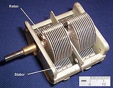
In electrical engineering, a capacitor is a device that stores electrical energy by accumulating electric charges on two closely spaced surfaces that are insulated from each other. It is a passive electronic component with two terminals.

<span class="mw-page-title-main">Trimmer (electronics)</span> Miniature adjustable component

A trimmer, or preset, is a miniature adjustable electrical component. It is meant to be set correctly when installed in some device, and never seen or adjusted by the device's user. Trimmers can be variable resistors (potentiometers), variable capacitors, or trimmable inductors. They are common in precision circuitry like A/V components, and may need to be adjusted when the equipment is serviced. Trimpots are often used to initially calibrate equipment after manufacturing. Unlike many other variable controls, trimmers are mounted directly on circuit boards, turned with a small screwdriver and rated for many fewer adjustments over their lifetime. Trimmers like trimmable inductors and trimmable capacitors are usually found in superhet radio and television receivers, in the intermediate frequency (IF), oscillator and radio frequency (RF) circuits. They are adjusted into the right position during the alignment procedure of the receiver.

<span class="mw-page-title-main">Plate detector (radio)</span>

In electronics, a plate detector is a vacuum tube circuit in which an amplifying tube having a control grid is operated in a non-linear region of its grid voltage versus plate current transfer characteristic, usually near plate current cutoff, to demodulate amplitude modulated carrier signal. This differs from the grid leak detector, which utilizes the non-linearity of the grid voltage versus grid current characteristic for demodulation. It also differs from the diode detector, which is a two-terminal device.

<span class="mw-page-title-main">Applications of capacitors</span> Uses of capacitors in daily life

Capacitors have many uses in electronic and electrical systems. They are so ubiquitous that it is rare that an electrical product does not include at least one for some purpose. Capacitors allow only AC signals to pass when they are charged blocking DC signals. The main components of filters are capacitors. Capacitors have the ability to connect one circuit segment to another. Capacitors are used by Dynamic Random Access Memory (DRAM) devices to represent binary information as bits.

This glossary of electrical and electronics engineering is a list of definitions of terms and concepts related specifically to electrical engineering and electronics engineering. For terms related to engineering in general, see Glossary of engineering.

References

  1. George Washington Pierce: Principles of wireless telegraphy, McGraw-Hill book company, New York, 1910, p. 114. (Photo of rotary capacitor of Korda).
  2. Frenzel, Louis (29 January 2009). "Automatic Digital Antenna Tuning Fits Multiple Wireless Applications". Electronic Design. Archived from the original on 3 August 2014. Retrieved 23 January 2017.