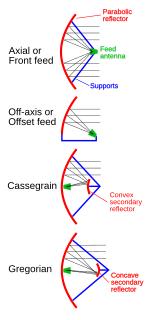
In telecommunications and radar, a Cassegrain antenna is a parabolic antenna in which the feed antenna is mounted at or behind the surface of the concave main parabolic reflector dish and is aimed at a smaller convex secondary reflector suspended in front of the primary reflector. The beam of radio waves from the feed illuminates the secondary reflector, which reflects it back to the main reflector dish, which reflects it forward again to form the desired beam. The Cassegrain design is widely used in parabolic antennas, particularly in large antennas such as those in satellite ground stations, radio telescopes, and communication satellites.

In telecommunications and electrical engineering, electrical length refers to the length of an electrical conductor in terms of the phase shift introduced by transmission over that conductor at some frequency.

In radio engineering, an antenna is the interface between radio waves propagating through space and electric currents moving in metal conductors, used with a transmitter or receiver. In transmission, a radio transmitter supplies an electric current to the antenna's terminals, and the antenna radiates the energy from the current as electromagnetic waves. In reception, an antenna intercepts some of the power of a radio wave in order to produce an electric current at its terminals, that is applied to a receiver to be amplified. Antennas are essential components of all radio equipment.

A parabolic antenna is an antenna that uses a parabolic reflector, a curved surface with the cross-sectional shape of a parabola, to direct the radio waves. The most common form is shaped like a dish and is popularly called a dish antenna or parabolic dish. The main advantage of a parabolic antenna is that it has high directivity. It functions similarly to a searchlight or flashlight reflector to direct the radio waves in a narrow beam, or receive radio waves from one particular direction only. Parabolic antennas have some of the highest gains, meaning that they can produce the narrowest beamwidths, of any antenna type. In order to achieve narrow beamwidths, the parabolic reflector must be much larger than the wavelength of the radio waves used, so parabolic antennas are used in the high frequency part of the radio spectrum, at UHF and microwave (SHF) frequencies, at which the wavelengths are small enough that conveniently-sized reflectors can be used.

A Yagi–Uda antenna, commonly known as a Yagi antenna, is a directional antenna consisting of multiple parallel elements in a line, usually half-wave dipoles made of metal rods. Yagi–Uda antennas consist of a single driven element connected to the transmitter or receiver with a transmission line, and additional "parasitic elements" which are not connected to the transmitter or receiver: a so-called reflector and one or more directors. It was invented in 1926 by Shintaro Uda of Tohoku Imperial University, Japan, and Hidetsugu Yagi.

A directional antenna or beam antenna is an antenna which radiates or receives greater power in specific directions allowing increased performance and reduced interference from unwanted sources. Directional antennas provide increased performance over dipole antennas—or omnidirectional antennas in general—when greater concentration of radiation in a certain direction is desired.

A helical antenna is an antenna consisting of one or more conducting wires wound in the form of a helix. In most cases, directional helical antennas are mounted over a ground plane, while omnidirectional designs may not be. The feed line is connected between the bottom of the helix and the ground plane. Helical antennas can operate in one of two principal modes — normal mode or axial mode.

In radio and telecommunications a dipole antenna or doublet is the simplest and most widely used class of antenna. The dipole is any one of a class of antennas producing a radiation pattern approximating that of an elementary electric dipole with a radiating structure supporting a line current so energized that the current has only one node at each end. A dipole antenna commonly consists of two identical conductive elements such as metal wires or rods. The driving current from the transmitter is applied, or for receiving antennas the output signal to the receiver is taken, between the two halves of the antenna. Each side of the feedline to the transmitter or receiver is connected to one of the conductors. This contrasts with a monopole antenna, which consists of a single rod or conductor with one side of the feedline connected to it, and the other side connected to some type of ground. A common example of a dipole is the "rabbit ears" television antenna found on broadcast television sets.
In a radio antenna, a passive radiator or parasitic element is a conductive element, typically a metal rod, which is not electrically connected to anything else. Multielement antennas such as the Yagi-Uda antenna typically consist of a "driven element" which is connected to the radio receiver or transmitter through a feed line, and parasitic elements, which are not. The purpose of the parasitic elements is to modify the radiation pattern of the radio waves emitted by the driven element, directing them in a beam in one direction, increasing the antenna's directivity (gain). A parasitic element does this by acting as a passive resonator, something like a guitar's sound box, absorbing the radio waves from the nearby driven element and re-radiating them again with a different phase. The waves from the different antenna elements interfere, strengthening the antenna's radiation in the desired direction, and cancelling out the waves in undesired directions.

A horn antenna or microwave horn is an antenna that consists of a flaring metal waveguide shaped like a horn to direct radio waves in a beam. Horns are widely used as antennas at UHF and microwave frequencies, above 300 MHz. They are used as feed antennas for larger antenna structures such as parabolic antennas, as standard calibration antennas to measure the gain of other antennas, and as directive antennas for such devices as radar guns, automatic door openers, and microwave radiometers. Their advantages are moderate directivity, low standing wave ratio (SWR), broad bandwidth, and simple construction and adjustment.

A T-antenna, T-aerial, flat-top antenna, or top-hat antenna is a capacitively loaded monopole wire radio antenna used in the VLF, LF, MF and shortwave bands. T-antennas are widely used as transmitting antennas for amateur radio stations, long wave and medium wave broadcasting stations. They are also used as receiving antennas for shortwave listening.
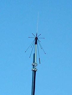
A discone antenna is a version of a biconical antenna in which one of the cones is replaced by a disc. It is usually mounted vertically, with the disc at the top and the cone beneath.

An antenna reflector is a device that reflects electromagnetic waves. Antenna reflectors can exist as a standalone device for redirecting radio frequency (RF) energy, or can be integrated as part of an antenna assembly.
Near vertical incidence skywave, or NVIS, is a skywave radio-wave propagation path that provides usable signals in the range between groundwave and conventional skywave distances—usually 30–400 miles (50–650 km). It is used for military and paramilitary communications, broadcasting, especially in the tropics, and by radio amateurs for nearby contacts circumventing line-of-sight barriers. The radio waves travel near-vertically upwards into the ionosphere, where they are refracted back down and can be received within a circular region up to 650 km from the transmitter. If the frequency is too high, refraction fails to occur and if it is too low, absorption in the ionospheric D layer may reduce the signal strength.

A corner reflector antenna is a type of directional antenna used at VHF and UHF frequencies. It was invented by John D. Kraus in 1938. It consists of a dipole driven element mounted in front of two flat rectangular reflecting screens joined at an angle, usually 90°. Corner reflectors have moderate gain of 10-15 dB, high front-to-back ratio of 20-30 dB, and wide bandwidth.

An output coupler (OC) is the component of an optical resonator that allows the extraction of a portion of the light from the laser's intracavity beam. An output coupler most often consists of a partially reflective mirror, allowing a certain portion of the intracavity beam to transmit through. Other methods include the use of almost-totally reflective mirrors at each end of the cavity, emitting the beam either by focusing it into a small hole drilled in the center of one mirror, or by redirecting through the use of rotating mirrors, prisms, or other optical devices, causing the beam to bypass one of the end mirrors at a given time.

A turnstile antenna, or crossed-dipole antenna, is a radio antenna consisting of a set of two identical dipole antennas mounted at right angles to each other and fed in phase quadrature; the two currents applied to the dipoles are 90° out of phase. The name reflects the notion the antenna looks like a turnstile when mounted horizontally. The antenna can be used in two possible modes. In normal mode the antenna radiates horizontally polarized radio waves perpendicular to its axis. In axial mode the antenna radiates circularly polarized radiation along its axis.

An antenna array is a set of multiple connected antennas which work together as a single antenna, to transmit or receive radio waves. The individual antennas are usually connected to a single receiver or transmitter by feedlines that feed the power to the elements in a specific phase relationship. The radio waves radiated by each individual antenna combine and superpose, adding together to enhance the power radiated in desired directions, and cancelling to reduce the power radiated in other directions. Similarly, when used for receiving, the separate radio frequency currents from the individual antennas combine in the receiver with the correct phase relationship to enhance signals received from the desired directions and cancel signals from undesired directions. More sophisticated array antennas may have multiple transmitter or receiver modules, each connected to a separate antenna element or group of elements.
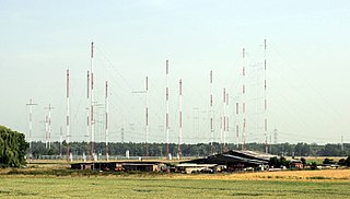
Curtain arrays are a class of large multielement directional wire radio transmitting antennas, used in the shortwave radio bands. They are a type of reflective array antenna, consisting of multiple wire dipole antennas, suspended in a vertical plane, often in front of a "curtain" reflector made of a flat vertical screen of many long parallel wires. These are suspended by support wires strung between pairs of tall steel towers, up to 300 ft (90 m) high. They are used for long-distance skywave transmission; they transmit a beam of radio waves at a shallow angle into the sky just above the horizon, which is reflected by the ionosphere back to Earth beyond the horizon. Curtain antennas are mostly used by international short wave radio stations to broadcast to large areas at transcontinental distances.
In radio systems, many different antenna types are used with specialized properties for particular applications. Antennas can be classified in various ways. The list below groups together antennas under common operating principles, following the way antennas are classified in many engineering textbooks.