
In electrical engineering, ground or earth may be a reference point in an electrical circuit from which voltages are measured, a common return path for electric current, or a direct physical connection to the Earth.

Medium wave (MW) is a part of the medium frequency (MF) radio band used mainly for AM radio broadcasting. The spectrum provides about 120 channels with more limited sound quality than FM stations on the FM broadcast band. During the daytime, reception is usually limited to more local stations, though this is dependent on the signal conditions and quality of radio receiver used. Improved signal propagation at night allows the reception of much longer distance signals. This can cause increased interference because on most channels multiple transmitters operate simultaneously worldwide. In addition, amplitude modulation (AM) is often more prone to interference by various electronic devices, especially power supplies and computers. Strong transmitters cover larger areas than on the FM broadcast band but require more energy and longer antennas. Digital modes are possible but have not reached momentum yet.

In radio engineering, an antenna or aerial is the interface between radio waves propagating through space and electric currents moving in metal conductors, used with a transmitter or receiver. In transmission, a radio transmitter supplies an electric current to the antenna's terminals, and the antenna radiates the energy from the current as electromagnetic waves. In reception, an antenna intercepts some of the power of a radio wave in order to produce an electric current at its terminals, that is applied to a receiver to be amplified. Antennas are essential components of all radio equipment.
Radiation resistance is that part of an antenna's feedpoint electrical resistance caused by the emission of radio waves from the antenna. A radio transmitter excites with a radio frequency alternating current an antenna, which radiates the exciting energy as radio waves. Because the antenna is absorbing the energy it is radiating from the transmitter, the antenna's input terminals present a resistance to the current from the transmitter.

In radio and telecommunications a dipole antenna or doublet is one of the two simplest and most widely-used types of antenna; the other is the monopole. The dipole is any one of a class of antennas producing a radiation pattern approximating that of an elementary electric dipole with a radiating structure supporting a line current so energized that the current has only one node at each far end. A dipole antenna commonly consists of two identical conductive elements such as metal wires or rods. The driving current from the transmitter is applied, or for receiving antennas the output signal to the receiver is taken, between the two halves of the antenna. Each side of the feedline to the transmitter or receiver is connected to one of the conductors. This contrasts with a monopole antenna, which consists of a single rod or conductor with one side of the feedline connected to it, and the other side connected to some type of ground. A common example of a dipole is the "rabbit ears" television antenna found on broadcast television sets. All dipoles are electrically equivalent to two monopoles mounted end-to-end and fed with opposite phases, with the ground plane between them made "virtual" by the opposing monopole.

A whip antenna is an antenna consisting of a straight flexible wire or rod. The bottom end of the whip is connected to the radio receiver or transmitter. A whip antenna is a form of monopole antenna. The antenna is designed to be flexible so that it does not break easily, and the name is derived from the whip-like motion that it exhibits when disturbed. Whip antennas for portable radios are often made of a series of interlocking telescoping metal tubes, so they can be retracted when not in use. Longer whips, made for mounting on vehicles and structures, are made of a flexible fiberglass rod around a wire core and can be up to 11 m long.

A guy-wire, guy-line, guy-rope, down guy, or stay, also called simply a guy, is a tensioned cable designed to add stability to a freestanding structure. They are used commonly for ship masts, radio masts, wind turbines, utility poles, and tents. A thin vertical mast supported by guy wires is called a guyed mast. Structures that support antennas are frequently of a lattice construction and are called "towers". One end of the guy is attached to the structure, and the other is anchored to the ground at some distance from the mast or tower base. The tension in the diagonal guy-wire, combined with the compression and buckling strength of the structure, allows the structure to withstand lateral loads such as wind or the weight of cantilevered structures. They are installed radially, usually at equal angles about the structure, in trios and quads. As the tower leans a bit due to the wind force, the increased guy tension is resolved into a compression force in the tower or mast and a lateral force that resists the wind load. For example, antenna masts are often held up by three guy-wires at 120° angles. Structures with predictable lateral loads, such as electrical utility poles, may require only a single guy-wire to offset the lateral pull of the electrical wires, at a spot where the wires change direction.

Radio masts and towers are typically tall structures designed to support antennas for telecommunications and broadcasting, including television. There are two main types: guyed and self-supporting structures. They are among the tallest human-made structures. Masts are often named after the broadcasting organizations that originally built them or currently use them.
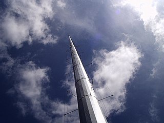
A mast radiator is a radio mast or tower in which the metal structure itself is energized and functions as an antenna. This design, first used widely in the 1930s, is commonly used for transmitting antennas operating at low frequencies, in the LF and MF bands, in particular those used for AM radio broadcasting stations. The conductive steel mast is electrically connected to the transmitter. Its base is usually mounted on a nonconductive support to insulate it from the ground. A mast radiator is a form of monopole antenna.

A ‘T’-antenna, ‘T’-aerial, or flat-top antenna is a monopole radio antenna consisting of one or more horizontal wires suspended between two supporting radio masts or buildings and insulated from them at the ends. A vertical wire is connected to the center of the horizontal wires and hangs down close to the ground, connected to the transmitter or receiver. The shape of the antenna resembles the letter "T", hence the name. The transmitter power is applied, or the receiver is connected, between the bottom of the vertical wire and a ground connection.

The J-pole antenna, more properly known as the J antenna, is a vertical omnidirectional transmitting antenna used in the shortwave frequency bands. It was invented by Hans Beggerow in 1909 for use in Zeppelin airships. Trailed behind the airship, it consisted of a single one half wavelength long wire radiator, in series with a quarter-wave parallel transmission line tuning stub that matches the antenna impedance to the feedline. By 1936 this antenna began to be used for land-based transmitters with the radiating element and the matching section mounted vertically, giving it the shape of the letter "J", and by 1943 it was named the J antenna. When the radiating half-wave section is mounted horizontally, at right-angles to the quarter-wave matching stub, the variation is usually called a Zepp antenna.

A loop antenna is a radio antenna consisting of a loop or coil of wire, tubing, or other electrical conductor, that for transmitting is usually fed by a balanced power source or for receiving feeds a balanced load. Within this physical description there are two distinct types:
A monopole antenna is a class of radio antenna consisting of a straight rod-shaped conductor, often mounted perpendicularly over some type of conductive surface, called a ground plane. The driving signal from the transmitter is applied, or for receiving antennas the output signal to the receiver is taken, between the lower end of the monopole and the ground plane. One side of the antenna feedline is attached to the lower end of the monopole, and the other side is attached to the ground plane, which is often the Earth. This contrasts with a dipole antenna which consists of two identical rod conductors, with the signal from the transmitter applied between the two halves of the antenna.
In RF engineering, radial has three distinct meanings, both referring to lines which radiate from a radio antenna, but neither meaning is related to the other.
The folded unipole antenna is a type of monopole mast radiator antenna used as a transmitting antenna mainly in the medium wave band for AM radio broadcasting stations. It consists of a vertical metal rod or mast mounted over and connected at its base to a grounding system consisting of buried wires. The mast is surrounded by a "skirt" of vertical wires electrically attached at or near the top of the mast. The skirt wires are connected by a metal ring near the mast base, and the feedline feeding power from the transmitter is connected between the ring and the ground.

Aviation obstruction lighting is used to enhance the visibility of structures or fixed obstacles which may conflict with the safe navigation of aircraft. Obstruction lighting is commonly installed on towers, buildings, and even fences located in areas where aircraft may be operating at low altitudes. In certain areas, some aviation regulators mandate the installation, operation, color, and/or status notification of obstruction lighting. For maximum visibility and collision-avoidance, these lighting systems commonly employ one or more high-intensity strobe or LED devices which can be seen by pilots from many miles away from the obstruction.

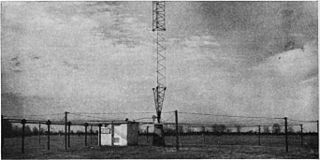
An umbrella antenna is a capacitively top-loaded wire monopole antenna, consisting in most cases of a mast fed at the ground end, to which a number of radial wires are connected at the top, sloping downwards. One side of the feedline supplying power from the transmitter is connected to the mast, and the other side to a ground (Earthing) system of radial wires buried in the earth under the antenna. They are used as transmitting antennas below 1 MHz, in the MF, LF and particularly the VLF bands, at frequencies sufficiently low that it is impractical or infeasible to build a full size quarter-wave monopole antenna. The outer end of each radial wire, sloping down from the top of the antenna, is connected by an insulator to a supporting rope or cable anchored to the ground; the radial wires can also support the mast as guy wires. The radial wires make the antenna look like the wire frame of a giant umbrella hence the name.
In electronics and radio communication, a counterpoise is a network of suspended horizontal wires or cables, used as a substitute for an earth (ground) connection in a radio antenna system. It is used with radio transmitters or receivers when a normal earth ground cannot be used because of high soil resistance or when an antenna is mounted above ground level, for example, on a building. It usually consists of a single wire or network of horizontal wires, parallel to the ground, suspended above the ground under the antenna, connected to the receiver or transmitter's "ground" wire. The counterpoise functions as one plate of a large capacitor, with the conductive layers of the earth acting as the other plate.

A halo antenna, or halo, is a center-fed 1 /2 wavelength dipole antenna, which has been bent into a circle, with a break directly opposite the feed point. The dipole's ends are close, but do not touch, and their crossections may be broadened to form an air capacitor, whose spacing is used to adjust the antenna's resonant frequency. Most often mounted horizontally, this antenna's radiation is then approximately omnidirectional and horizontally polarized.
In radio systems, many different antenna types are used whose properties are especially crafted for particular applications. Most often, the greatest effect is due to the size (wavelength) of the radio waves the antenna is to intercept or produce; one competing second effect is differences in optimization for receiving and for transmitting; another competing influence is the number and bandwidth of the frequenc(y/ies) that any single antenna must intercept or emit.
