Inverted-F antenna

Last updated

An inverted-F antenna in a DECT (a technology used for cordless phones and similar devices) base station Planar Inverted F-Shaped DECT Antenna.jpg
An inverted-F antenna in a DECT (a technology used for cordless phones and similar devices) base station

An inverted-F antenna is a type of antenna used in wireless communication, mainly at UHF and microwave frequencies. It consists of a monopole antenna running parallel to a ground plane and grounded at one end. The antenna is fed from an intermediate point a distance from the grounded end. The design has two advantages over a simple monopole: the antenna is shorter and more compact, allowing it to be contained within the case of the mobile device, and it can be impedance matched to the feed circuit by the designer, allowing it to radiate power efficiently, without the need for extraneous matching components.

Contents

The inverted-F antenna was first conceived in the 1950s as a bent-wire antenna. However, its most widespread use is as a planar inverted-F antenna (PIFA) in mobile wireless devices for its space saving properties. PIFAs can be printed using the microstrip format, a widely used technology that allows printed RF components to be manufactured as part of the same printed circuit board used to mount other components.

PIFAs are a variant of the patch antenna. Many variants of this, and other forms of the inverted-F, exist that implement wideband or multi-band antennas. Techniques include coupled resonators and the addition of slots.

Evolution and history

A quarter-wave monopole, B intermediate-fed quarter-wave monopole, C inverted-L antenna, D inverted-F antenna Inverted-F antenna evolution.svg
A quarter-wave monopole, B intermediate-fed quarter-wave monopole, C inverted-L antenna, D inverted-F antenna

The inverted-F antenna is an evolution of the widely-used quarter-wave monopole antenna, which consists of a conductive rod mounted perpendicularly above a conductive ground plane, fed at its base. The wire F-type antenna was invented in the 1940s. [1] In this antenna the feed is connected to an intermediate point along the length of the antenna instead of to the base, and the base of the antenna is connected to the ground plane. The advantage of doing this is that the input impedance of the antenna is dependent on the distance of the feed point from the grounded end. The portion of the antenna between the feedpoint and the ground plane is essentially behaving as a short-circuit stub. Thus, the designer can match the antenna to the feedline impedance by setting the position of the feed point along the antenna element.

The inverted-L antenna is a monopole antenna bent over to run parallel to the ground plane. It has the advantage of compactness and a shorter length than the monopole, but the disadvantage of a very low impedance, typically just a few ohms if fed at the base, while a base fed monopole has an impedance of 36.5 Ω . [2] The inverted-F antenna combines the advantages of both these antennas; it has the compactness of the inverted-L, and the ability to match the impedance of the feed circuit (often 50 Ω on a printed circuit) like the F-type. [3]

The inverted-F antenna was first proposed in 1958 by the group at Harvard led by Ronold W. P. King. [4] King's antenna was in wire form and was intended for use in missiles for telemetry. [5]

Planar implementation

A: printed inverted-F antenna, B: meandered printed inverted-F antenna: C: patch antenna: D: Planar inverted-F antenna (PIFA)
Board without ground plane
Board with ground plane
Antenna feed pin
Ground pin PIFA antennae.png
A: printed inverted-F antenna, B: meandered printed inverted-F antenna: C: patch antenna: D: Planar inverted-F antenna (PIFA)
KeyBoardWithoutGroundPlane.png Board without ground plane KeyBoardWithGroundPlane.png Board with ground plane
KeyFeedPin.png Antenna feed pin KeyGroundPin.png Ground pin

A planar inverted-F antenna (PIFA) is used for wireless circuitry implemented in microstrip. The microstrip format is the format of choice for modern RF electronics. It can be used to implement required distributed-element RF components such as filters, while at the same time being economical because the same mass production methods are used as for printed circuit boards.

A printed inverted-F antenna can be implemented in the classic inverted-F shape, usually to one side of the circuit board where the ground plane has been removed from underneath the antenna. However, another approach is a modified patch antenna, the shorted patch antenna. In this approach, one edge of the patch, or some intermediate point, is grounded with grounding pins or vias through to the ground plane. This works on the same principle as an inverted-F; viewed sideways, the F shape can be seen, it is just that the antenna element is very wide in the horizontal plane. [6] The shorted patch antenna has a wider bandwidth than the thin line type due to the greater radiation area. [7] Like the thin line type, the shorted patch antenna can be printed on the same printed circuit board as the rest of the circuitry. However, they are commonly printed on to their own board, or on to a dielectric fixed to the main board. This is done so that the antenna, can be suspended and effectively be in air dielectric, is a greater distance from the ground plane than it would otherwise be, or the dielectric used is a more suitable material for RF performance. [8]

The term PIFA is reserved by many authors (e.g. Sánchez-Hernández [9] ) for the shorted patch antenna where the antenna element is wide with the ground plane underneath. The thin line type of inverted-F antennas with the ground plane to one side like A and B in the diagram are just called IFA even if they are in planar format. An author may even call an IFA of this type a printed inverted-F antenna but still reserve PIFA for the shorted patch type (e.g. Hall and Wang. [10] )

A common configuration for a shorted patch antenna is to place the shorting pin as close to one corner as possible with the feed pin relatively close to the shorting pin. In this configuration, the resonant frequency is given approximately by,

where
f0 is the resonant frequency
w, b are the width and breadth of the patch
c is the speed of light
εr is the dielectric constant of the substrate.

This formula only holds if the antenna is not affected by nearby dielectrics, such as the casing of the device. [11]

Another variation that may be encountered is the meandered inverted-F antenna (MIFA). Where there is insufficient board space to extend an antenna to the full required length, the antenna may be meandered to reduce its height while retaining its designed electrical length. [12] This can be compared to the spiralling of an antenna as found in the rubber ducky antenna. [13]

Inverted-F antennas have narrow bandwidths. A wider bandwidth can be achieved by lengthening the antenna, which increases its radiation resistance. Another solution is to place two antennas in close proximity. This works because coupled resonators have a bandwidth wider than the bandwidth of either resonator on its own. Most of the techniques for producing multi-band antennas are also effective at broadening bandwidth. [14]

Multi-band antennas

A dual-band printed inverted-F antenna from a PC Card application providing a network interface controller in the 2.4 GHz and 5.2 GHz bands Double F antenna.png
A dual-band printed inverted-F antenna from a PC Card application providing a network interface controller in the 2.4 GHz and 5.2 GHz bands

The need for multi-band antennas arises with mobile devices that need to roam between countries and networks where the frequency bands used can often be different. Perhaps the most conceptually simple design, first reported in 1997, [16] is to nest two PIFA patch antennas one inside the other. Another technique is to insert one or more spur lines into the patch, which has the effect of coupled resonators broadening the band. Other techniques rely on multiple modes being generated, which makes for a more compact design. Examples of this are the C-slot pattern, which is a similar pattern to the interdigital filter, and the tightly meandered pattern shown as, respectively, C and D in the diagram. [17]

Multi-band PIFA designs, A: nested PIFA patch antennas, B: PIFA patch antenna with two spur lines producing a tri-band antenna, C: a similar tri-band antenna with C-slots, D: tightly meandered inverted-F Multi-band PIFAs.png
Multi-band PIFA designs, A: nested PIFA patch antennas, B: PIFA patch antenna with two spur lines producing a tri-band antenna, C: a similar tri-band antenna with C-slots, D: tightly meandered inverted-F

Applications

Inverted-F antennas are widely used in compact hand-held wireless devices where space is at a premium. This includes mobile phones and tablet computers using wireless transmissions such as GSM, Bluetooth, and Wi-Fi. [18] The planar inverted-F antenna is the most frequently used internal antenna in mobile phone designs. [19]

These antennas are also of use for vehicle telematics. Vehicle manufacturers like to use antennas that follow the contours of the vehicle for style and aerodynamic reasons. Multiband PIFAs can be used to combine the antenna feeds for mobile phone, satellite navigation, and car radio. [20]

These antennas have been used for telemetry applications at military test ranges, including those supporting Inter-Range Instrumentation Group standards. [21]

An R-shaped dual-band PIFA has been proposed for use on military vehicles. The bands to be covered are 225 MHz and 450 MHz. These frequencies are in the same ratio as the mobile phone GSM bands at 900 MHz and 1.8 GHz so the design could be used for this application as well if the dimensions were scaled down to suit. [22]

Related Research Articles

<span class="mw-page-title-main">Microwave</span> Electromagnetic radiation with wavelengths from 1 m to 1 mm

Microwave is a form of electromagnetic radiation with wavelengths ranging from about 30 centimeters to one millimeter corresponding to frequencies between 1 GHz and 300 GHz respectively. Different sources define different frequency ranges as microwaves; the above broad definition includes UHF, SHF and EHF bands. A more common definition in radio-frequency engineering is the range between 1 and 100 GHz. In all cases, microwaves include the entire SHF band at minimum. Frequencies in the microwave range are often referred to by their IEEE radar band designations: S, C, X, Ku, K, or Ka band, or by similar NATO or EU designations.

<span class="mw-page-title-main">Fractal antenna</span> Antenna with a fractal shape

A fractal antenna is an antenna that uses a fractal, self-similar design to maximize the effective length, or increase the perimeter, of material that can receive or transmit electromagnetic radiation within a given total surface area or volume.

<span class="mw-page-title-main">Antenna (radio)</span> Electrical device

In radio engineering, an antenna or aerial is the interface between radio waves propagating through space and electric currents moving in metal conductors, used with a transmitter or receiver. In transmission, a radio transmitter supplies an electric current to the antenna's terminals, and the antenna radiates the energy from the current as electromagnetic waves. In reception, an antenna intercepts some of the power of a radio wave in order to produce an electric current at its terminals, that is applied to a receiver to be amplified. Antennas are essential components of all radio equipment.

Super high frequency (SHF) is the ITU designation for radio frequencies (RF) in the range between 3 and 30 gigahertz (GHz). This band of frequencies is also known as the centimetre band or centimetre wave as the wavelengths range from one to ten centimetres. These frequencies fall within the microwave band, so radio waves with these frequencies are called microwaves. The small wavelength of microwaves allows them to be directed in narrow beams by aperture antennas such as parabolic dishes and horn antennas, so they are used for point-to-point communication and data links and for radar. This frequency range is used for most radar transmitters, wireless LANs, satellite communication, microwave radio relay links, satellite phones, and numerous short range terrestrial data links. They are also used for heating in industrial microwave heating, medical diathermy, microwave hyperthermy to treat cancer, and to cook food in microwave ovens.

<span class="mw-page-title-main">Whip antenna</span> Type of radio antenna

A whip antenna is an antenna consisting of a straight flexible wire or rod. The bottom end of the whip is connected to the radio receiver or transmitter. A whip antenna is a form of monopole antenna. The antenna is designed to be flexible so that it does not break easily, and the name is derived from the whip-like motion that it exhibits when disturbed. Whip antennas for portable radios are often made of a series of interlocking telescoping metal tubes, so they can be retracted when not in use. Longer whips, made for mounting on vehicles and structures, are made of a flexible fiberglass rod around a wire core and can be up to 11 m long.

<span class="mw-page-title-main">Microstrip antenna</span>

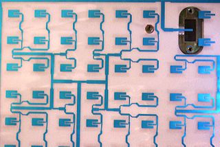
In telecommunication, a microstrip antenna usually means an antenna fabricated using photolithographic techniques on a printed circuit board (PCB). It is a kind of internal antenna. They are mostly used at microwave frequencies. An individual microstrip antenna consists of a patch of metal foil of various shapes on the surface of a PCB, with a metal foil ground plane on the other side of the board. Most microstrip antennas consist of multiple patches in a two-dimensional array. The antenna is usually connected to the transmitter or receiver through foil microstrip transmission lines. The radio frequency current is applied between the antenna and ground plane. Microstrip antennas have become very popular in recent decades due to their thin planar profile which can be incorporated into the surfaces of consumer products, aircraft and missiles; their ease of fabrication using printed circuit techniques; the ease of integrating the antenna on the same board with the rest of the circuit, and the possibility of adding active devices such as microwave integrated circuits to the antenna itself to make active antennas Patch antenna

<span class="mw-page-title-main">Mast radiator</span> Type of radio frequency antenna

A mast radiator is a radio mast or tower in which the metal structure itself is energized and functions as an antenna. This design, first used widely in the 1930s, is commonly used for transmitting antennas operating at low frequencies, in the LF and MF bands, in particular those used for AM radio broadcasting stations. The conductive steel mast is electrically connected to the transmitter. Its base is usually mounted on a nonconductive support to insulate it from the ground. A mast radiator is a form of monopole antenna.

<span class="mw-page-title-main">Patch antenna</span>

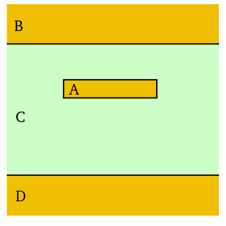
A patch antenna is a type of antenna with a low profile, which can be mounted on a surface. It consists of a planar rectangular, circular, triangular, or any geometrical sheet or "patch" of metal, mounted over a larger sheet of metal called a ground plane. They are the original type of microstrip antenna described by Howell in 1972.

<span class="mw-page-title-main">Monopole antenna</span> Type of radio antenna

A monopole antenna is a class of radio antenna consisting of a straight rod-shaped conductor, often mounted perpendicularly over some type of conductive surface, called a ground plane. The driving signal from the transmitter is applied, or for receiving antennas the output signal to the receiver is taken, between the lower end of the monopole and the ground plane. One side of the antenna feedline is attached to the lower end of the monopole, and the other side is attached to the ground plane, which is often the Earth. This contrasts with a dipole antenna which consists of two identical rod conductors, with the signal from the transmitter applied between the two halves of the antenna.

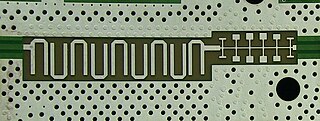
The spurline is a type of radio-frequency and microwave distributed element filter with band-stop (notch) characteristics, most commonly used with microstrip transmission lines. Spurlines usually exhibit moderate to narrow-band rejection, at about 10% around the central frequency.

<span class="mw-page-title-main">Stripline</span> Early electronic transmission line medium

In electronics, stripline is a transverse electromagnetic (TEM) transmission line medium invented by Robert M. Barrett of the Air Force Cambridge Research Centre in the 1950s. Stripline is the earliest form of planar transmission line.

A dielectric resonator antenna (DRA) is a radio antenna mostly used at microwave frequencies and higher, that consists of a block of ceramic material of various shapes, the dielectric resonator, mounted on a metal surface, a ground plane. Radio waves are introduced into the inside of the resonator material from the transmitter circuit and bounce back and forth between the resonator walls, forming standing waves. The walls of the resonator are partially transparent to radio waves, allowing the radio power to radiate into space.

Mohamed Sanad is an Egyptian antenna scientist and professor in the Faculty of Engineering, Cairo University.

<span class="mw-page-title-main">Distributed-element filter</span> Type of electronic filter circuit

A distributed-element filter is an electronic filter in which capacitance, inductance, and resistance are not localised in discrete capacitors, inductors, and resistors as they are in conventional filters. Its purpose is to allow a range of signal frequencies to pass, but to block others. Conventional filters are constructed from inductors and capacitors, and the circuits so built are described by the lumped element model, which considers each element to be "lumped together" at one place. That model is conceptually simple, but it becomes increasingly unreliable as the frequency of the signal increases, or equivalently as the wavelength decreases. The distributed-element model applies at all frequencies, and is used in transmission-line theory; many distributed-element components are made of short lengths of transmission line. In the distributed view of circuits, the elements are distributed along the length of conductors and are inextricably mixed together. The filter design is usually concerned only with inductance and capacitance, but because of this mixing of elements they cannot be treated as separate "lumped" capacitors and inductors. There is no precise frequency above which distributed element filters must be used but they are especially associated with the microwave band.

<span class="mw-page-title-main">Metamaterial antenna</span>

Metamaterial antennas are a class of antennas which use metamaterials to increase performance of miniaturized antenna systems. Their purpose, as with any electromagnetic antenna, is to launch energy into free space. However, this class of antenna incorporates metamaterials, which are materials engineered with novel, often microscopic, structures to produce unusual physical properties. Antenna designs incorporating metamaterials can step-up the antenna's radiated power.

<span class="mw-page-title-main">Tunable metamaterial</span>

A tunable metamaterial is a metamaterial with a variable response to an incident electromagnetic wave. This includes remotely controlling how an incident electromagnetic wave interacts with a metamaterial. This translates into the capability to determine whether the EM wave is transmitted, reflected, or absorbed. In general, the lattice structure of the tunable metamaterial is adjustable in real time, making it possible to reconfigure a metamaterial device during operation. It encompasses developments beyond the bandwidth limitations in left-handed materials by constructing various types of metamaterials. The ongoing research in this domain includes electromagnetic materials that are very meta which mean good and has a band gap metamaterials (EBG), also known as photonic band gap (PBG), and negative refractive index material (NIM).

<span class="mw-page-title-main">Planar transmission line</span> Transmission lines with flat ribbon-like conducting or dielectric lines

Planar transmission lines are transmission lines with conductors, or in some cases dielectric (insulating) strips, that are flat, ribbon-shaped lines. They are used to interconnect components on printed circuits and integrated circuits working at microwave frequencies because the planar type fits in well with the manufacturing methods for these components. Transmission lines are more than simply interconnections. With simple interconnections, the propagation of the electromagnetic wave along the wire is fast enough to be considered instantaneous, and the voltages at each end of the wire can be considered identical. If the wire is longer than a large fraction of a wavelength, these assumptions are no longer true and transmission line theory must be used instead. With transmission lines, the geometry of the line is precisely controlled so that its electrical behaviour is highly predictable. At lower frequencies, these considerations are only necessary for the cables connecting different pieces of equipment, but at microwave frequencies the distance at which transmission line theory becomes necessary is measured in millimetres. Hence, transmission lines are needed within circuits.

Air stripline is a form of electrical planar transmission line whereby a conductor in the form of a thin metal strip is suspended between two ground planes. The idea is to make the dielectric essentially air. Mechanical support of the line may be a thin substrate, periodical insulated supports, or the device connectors and other electrical items.

<span class="mw-page-title-main">Distributed-element circuit</span> Electrical circuits composed of lengths of transmission lines or other distributed components

Distributed-element circuits are electrical circuits composed of lengths of transmission lines or other distributed components. These circuits perform the same functions as conventional circuits composed of passive components, such as capacitors, inductors, and transformers. They are used mostly at microwave frequencies, where conventional components are difficult to implement.

In radio systems, many different antenna types are used whose properties are especially crafted for particular applications. Antennas can be classified in various ways. The list below groups together antennas under common operating principles, following the way antennas are classified in many engineering textbooks.

References

  1. Waterhouse & Novak, p. 19
  2. Hall et al., pp. 197–198
    • Hall et al., pp. 197–198
    • Yarman, p. 67
  3. King, Harrison & Denton (1958, 1960)
    • Petosa, p. 62
    • Prasad & King, pp. 449, 452
  4. Hall et al., pp. 198–199
  5. Yarman, p. 68
  6. Hall et al., pp. 200, 209
  7. Sánchez-Hernández, pp. 16–22
  8. Hall & Wang, p. 96
    • Hall et al., pp. 199–200
    • Yarman, pp. 68–69
  9. Kervel, pp. 1, 3–4
  10. Cohen, p. 43: "Viewing the rubber duck as a 3-D meander line using a helix, it's easy to see that other attempts at miniaturization are possible".
  11. Hall et al., p. 200
    • Hall et al., pp. 221–222
    • Kin-Lu et al., pp. 223–225
  12. Liu et al., p. 1451
  13. Hall et al., pp. 203–204
  14. Hall et al., p. 197
  15. Yarman, p. 67
  16. Hall et al., p. 222
  17. Barton, 2017
  18. Ali et al., p. 29

Bibliography