
Radio navigation or radionavigation is the application of radio frequencies to determine a position of an object on the Earth, either the vessel or an obstruction. Like radiolocation, it is a type of radiodetermination.
Very low frequency or VLF is the ITU designation for radio frequencies (RF) in the range of 3–30 kHz, corresponding to wavelengths from 100 to 10 km, respectively. The band is also known as the myriameter band or myriameter wave as the wavelengths range from one to ten myriameters. Due to its limited bandwidth, audio (voice) transmission is highly impractical in this band, and therefore only low data rate coded signals are used. The VLF band is used for a few radio navigation services, government time radio stations and for secure military communication. Since VLF waves can penetrate at least 40 meters (131 ft) into saltwater, they are used for military communication with submarines.
Low frequency (LF) is the ITU designation for radio frequencies (RF) in the range of 30–300 kHz. Since its wavelengths range from 10–1 km, respectively, it is also known as the kilometre band or kilometre wave.

High frequency (HF) is the ITU designation for the range of radio frequency electromagnetic waves between 3 and 30 megahertz (MHz). It is also known as the decameter band or decameter wave as its wavelengths range from one to ten decameters. Frequencies immediately below HF are denoted medium frequency (MF), while the next band of higher frequencies is known as the very high frequency (VHF) band. The HF band is a major part of the shortwave band of frequencies, so communication at these frequencies is often called shortwave radio. Because radio waves in this band can be reflected back to Earth by the ionosphere layer in the atmosphere – a method known as "skip" or "skywave" propagation – these frequencies are suitable for long-distance communication across intercontinental distances and for mountainous terrains which prevent line-of-sight communications. The band is used by international shortwave broadcasting stations (3.95–25.82 MHz), aviation communication, government time stations, weather stations, amateur radio and citizens band services, among other uses.

In radio engineering, an antenna or aerial is the interface between radio waves propagating through space and electric currents moving in metal conductors, used with a transmitter or receiver. In transmission, a radio transmitter supplies an electric current to the antenna's terminals, and the antenna radiates the energy from the current as electromagnetic waves. In reception, an antenna intercepts some of the power of a radio wave in order to produce an electric current at its terminals, that is applied to a receiver to be amplified. Antennas are essential components of all radio equipment.

A non-directional beacon (NDB) or non-directional radio beacon is a radio beacon which does not include inherent directional information. Radio beacons are radio transmitters at a known location, used as an aviation or marine navigational aid. NDB are in contrast to directional radio beacons and other navigational aids, such as low-frequency radio range, VHF omnidirectional range (VOR) and tactical air navigation system (TACAN).

A helical antenna is an antenna consisting of one or more conducting wires wound in the form of a helix. A helical antenna made of one helical wire, the most common type, is called monofilar, while antennas with two or four wires in a helix are called bifilar, or quadrifilar, respectively.

Direction finding (DF), or radio direction finding (RDF), is – in accordance with International Telecommunication Union (ITU) – defined as radio location that uses the reception of radio waves to determine the direction in which a radio station or an object is located. This can refer to radio or other forms of wireless communication, including radar signals detection and monitoring (ELINT/ESM). By combining the direction information from two or more suitably spaced receivers, the source of a transmission may be located via triangulation. Radio direction finding is used in the navigation of ships and aircraft, to locate emergency transmitters for search and rescue, for tracking wildlife, and to locate illegal or interfering transmitters. RDF was important in combating German threats during both the World War II Battle of Britain and the long running Battle of the Atlantic. In the former, the Air Ministry also used RDF to locate its own fighter groups and vector them to detected German raids.

High-frequency direction finding, usually known by its abbreviation HF/DF or nickname huff-duff, is a type of radio direction finder (RDF) introduced in World War II. High frequency (HF) refers to a radio band that can effectively communicate over long distances; for example, between U-boats and their land-based headquarters. HF/DF was primarily used to catch enemy radios while they transmitted, although it was also used to locate friendly aircraft as a navigation aid. The basic technique remains in use as one of the fundamental disciplines of signals intelligence, although typically incorporated into a larger suite of radio systems and radars instead of being a stand-alone system.

A slot antenna consists of a metal surface, usually a flat plate, with one or more holes or slots cut out. When the plate is driven as an antenna by an applied radio frequency current, the slot radiates electromagnetic waves in a way similar to a dipole antenna. The shape and size of the slot, as well as the driving frequency, determine the radiation pattern. Slot antennas are usually used at UHF and microwave frequencies at which wavelengths are small enough that the plate and slot are conveniently small. At these frequencies, the radio waves are often conducted by a waveguide, and the antenna consists of slots in the waveguide; this is called a slotted waveguide antenna. Multiple slots act as a directive array antenna and can emit a narrow fan-shaped beam of microwaves. They are used in standard laboratory microwave sources used for research, UHF television transmitting antennas, antennas on missiles and aircraft, sector antennas for cellular base stations, and particularly marine radar antennas. A slot antenna's main advantages are its size, design simplicity, and convenient adaptation to mass production using either waveguide or PC board technology.

A discone antenna is a version of a biconical antenna in which one of the cones is replaced by a disc. It is usually mounted vertically, with the disc at the top and the cone beneath.
A loop antenna is a radio antenna consisting of a loop or coil of wire, tubing, or other electrical conductor, that for transmitting is usually fed by a balanced power source or for receiving feeds a balanced load. Within this physical description there are two distinct types:

A monopole antenna is a class of radio antenna consisting of a straight rod-shaped conductor, often mounted perpendicularly over some type of conductive surface, called a ground plane. The driving signal from the transmitter is applied, or for receiving antennas the output signal to the receiver is taken, between the lower end of the monopole and the ground plane. One side of the antenna feedline is attached to the lower end of the monopole, and the other side is attached to the ground plane, which is often the Earth. This contrasts with a dipole antenna which consists of two identical rod conductors, with the signal from the transmitter applied between the two halves of the antenna.

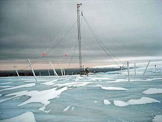
An umbrella antenna is a capacitively top-loaded wire monopole antenna, consisting in most cases of a mast fed at the ground end, to which a number of radial wires are connected at the top, sloping downwards. They are used as transmitting antennas below 1 MHz, in the MF, LF and particularly the VLF bands, at frequencies sufficiently low that it is impractical or infeasible to build a full size quarter-wave monopole antenna. The outer end of each radial wire, sloping down from the top of the antenna, is connected by an insulator to a supporting rope or (usually) insulated cable anchored to the ground; the radial wires can also support the mast as guy wires. The radial wires make the antenna look like the wire frame of a giant umbrella hence the name.

A turnstile antenna, or crossed-dipole antenna, is a radio antenna consisting of a set of two identical dipole antennas mounted at right angles to each other and fed in phase quadrature; the two currents applied to the dipoles are 90° out of phase. The name reflects the notion the antenna looks like a turnstile when mounted horizontally. The antenna can be used in two possible modes. In normal mode the antenna radiates horizontally polarized radio waves perpendicular to its axis. In axial mode the antenna radiates circularly polarized radiation along its axis.

Radio is the technology of signaling and communicating using radio waves. Radio waves are electromagnetic waves of frequency between 3 hertz (Hz) and 3,000 gigahertz (GHz). They are generated by an electronic device called a transmitter connected to an antenna which radiates the waves, and received by another antenna connected to a radio receiver. Radio is widely used in modern technology, in radio communication, radar, radio navigation, remote control, remote sensing, and other applications.

The low-frequency radio range, also known as the four-course radio range, LF/MF four-course radio range, A-N radio range, Adcock radio range, or commonly "the range", was the main navigation system used by aircraft for instrument flying in the 1930s and 1940s, until the advent of the VHF omnidirectional range (VOR), beginning in the late 1940s. It was used for en route navigation as well as instrument approaches and holds.
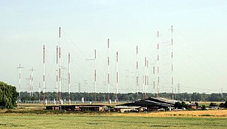
Curtain arrays are a class of large multielement directional radio transmitting wire antennas, used in the shortwave radio bands. They are a type of reflective array antenna, consisting of multiple wire dipole antennas, suspended in a vertical plane, often in front of a "curtain" reflector made of a flat vertical screen of many long parallel wires. These are suspended by support wires strung between pairs of tall steel towers, up to 90 m high. They are used for long-distance skywave transmission; they transmit a beam of radio waves at a shallow angle into the sky just above the horizon, which is reflected by the ionosphere back to Earth beyond the horizon. Curtain antennas are mostly used by international short wave radio stations to broadcast to large areas at transcontinental distances.

A Bellini–Tosi direction finder is a type of radio direction finder (RDF), which determines the direction to, or bearing of, a radio transmitter. Earlier RDF systems used very large rotating loop antennas, which the B–T system replaced with two fixed antennae and a small rotating loop, known as a radiogoniometer. This made RDF much more practical, especially on large vehicles like ships or when using very long wavelengths that demand large antennae.
In radio systems, many different antenna types are used whose properties are especially crafted for particular applications. Antennas can be classified in various ways. The list below groups together antennas under common operating principles, following the way antennas are classified in many engineering textbooks.


