

The Moxon antenna or Moxon Rectangle is a simple and mechanically robust two-element parasitic array, single-frequency antenna. [1] It takes its name from the amateur radio operator and antenna handbook author Les Moxon [2] (call sign G6XN). [1]
The Moxon antenna or Moxon Rectangle is a simple and mechanically robust two-element parasitic array, single-frequency antenna. [1] It takes its name from the amateur radio operator and antenna handbook author Les Moxon [2] (call sign G6XN). [1]

The Moxon antenna design is rectangular, with slightly less than half of the rectangle being the driven element (radiator) and the other part (slightly more than half) being the reflector. It is a two element Yagi-Uda antenna with folded dipole elements, and with no director(s).
Because of the folded ends, the element lengths are approximately 70% of the equivalent dipole length. The two-element design gives modest directivity (about 2.0 dB) with a null towards the rear of the antenna, yielding a high front-to-back ratio: Gain up to 9.7 dBi can be achieved at 28 MHz. [3] Because the placement and size of the parasitic reflector both depend highly on wavelength, each Moxon antenna functions properly on the frequency band for which it is designed.
Portable Moxon rectangles are favored by radio amateurs for field day and for emergency communications use because of their light weight and robust construction.[ citation needed ]
The Moxon antenna is popular with amateur radio enthusiasts for its simplicity of construction. The drawing shows the system of construction. The driven element to the left is slightly shorter than a half-wavelength, and the parasitic reflector on the right is slightly longer than a half-wavelength. The ends of the two are mechanically connected with an insulator (blue in the drawing). The antenna is in layout similar to the well known VK2ABQ-square. For use on shortwave bands, spreaders are commonly made of bamboo or glass-fiber reinforced plastics, carrying a radiator and reflector made from wire. Such antennas can be built with little wind load and minimal weight. For VHF and UHF Moxon antennas are small enough that they are more often made from around 3 /8 ~ 3 /4 inch diameter aluminum tubing, to take advantage of the broader resonant bandwidth, without suffering from excessive wind load.
L. B. Cebik (W4RNL) made detailed comparisons and calculations of several different versions of Moxon antennas. [4] Maguire (AC6LA) provides a calculator [5] which is based on empirical formulas developed by Cebik.

In telecommunications and radar, a reflective array antenna is a class of directive antennas in which multiple driven elements are mounted in front of a flat surface designed to reflect the radio waves in a desired direction. They are a type of array antenna. They are often used in the VHF and UHF frequency bands. VHF examples are generally large and resemble a highway billboard, so they are sometimes called billboard antennas. Other names are bedspring array and bowtie array depending on the type of elements making up the antenna. The curtain array is a larger version used by shortwave radio broadcasting stations.

In radio engineering, an antenna or aerial is the interface between radio waves propagating through space and electric currents moving in metal conductors, used with a transmitter or receiver. In transmission, a radio transmitter supplies an electric current to the antenna's terminals, and the antenna radiates the energy from the current as electromagnetic waves. In reception, an antenna intercepts some of the power of a radio wave in order to produce an electric current at its terminals, that is applied to a receiver to be amplified. Antennas are essential components of all radio equipment.

A Yagi–Uda antenna, or simply Yagi antenna, is a directional antenna consisting of two or more parallel resonant antenna elements in an end-fire array; these elements are most often metal rods acting as half-wave dipoles. Yagi–Uda antennas consist of a single driven element connected to a radio transmitter or receiver through a transmission line, and additional passive radiators with no electrical connection, usually including one so-called reflector and any number of directors. It was invented in 1926 by Shintaro Uda of Tohoku Imperial University, Japan, with a lesser role played by his boss Hidetsugu Yagi.

In radio communication, an omnidirectional antenna is a class of antenna which radiates equal radio power in all directions perpendicular to an axis, with power varying with angle to the axis, declining to zero on the axis. When graphed in three dimensions (see graph) this radiation pattern is often described as doughnut-shaped. This is different from an isotropic antenna, which radiates equal power in all directions, having a spherical radiation pattern. Omnidirectional antennas oriented vertically are widely used for nondirectional antennas on the surface of the Earth because they radiate equally in all horizontal directions, while the power radiated drops off with elevation angle so little radio energy is aimed into the sky or down toward the earth and wasted. Omnidirectional antennas are widely used for radio broadcasting antennas, and in mobile devices that use radio such as cell phones, FM radios, walkie-talkies, wireless computer networks, cordless phones, GPS, as well as for base stations that communicate with mobile radios, such as police and taxi dispatchers and aircraft communications.
The Tilted Terminated Folded Dipole or Balanced Termination, Folded Dipole (BTFD) - also known as W3HH antenna - is a general-purpose shortwave antenna developed in the late 1940s by the United States Navy. It performs reasonably well over a broad frequency range, without marked dead spots in terms of either frequency, direction, or angle of radiation above the horizon.

In radio and telecommunications a dipole antenna or doublet is the simplest and most widely used class of antenna. The dipole is any one of a class of antennas producing a radiation pattern approximating that of an elementary electric dipole with a radiating structure supporting a line current so energized that the current has only one node at each end. A dipole antenna commonly consists of two identical conductive elements such as metal wires or rods. The driving current from the transmitter is applied, or for receiving antennas the output signal to the receiver is taken, between the two halves of the antenna. Each side of the feedline to the transmitter or receiver is connected to one of the conductors. This contrasts with a monopole antenna, which consists of a single rod or conductor with one side of the feedline connected to it, and the other side connected to some type of ground. A common example of a dipole is the "rabbit ears" television antenna found on broadcast television sets.

A loop antenna is a radio antenna consisting of a loop or coil of wire, tubing, or other electrical conductor, that for transmitting is usually fed by a balanced power source or for receiving feeds a balanced load. Within this physical description there are two distinct types:
Near vertical incidence skywave, or NVIS, is a skywave radio-wave propagation path that provides usable signals in the medium distances range — usually 0–650 km. It is used for military and paramilitary communications, broadcasting, especially in the tropics, and by radio amateurs for nearby contacts circumventing line-of-sight barriers. The radio waves travel near-vertically upwards into the ionosphere, where they are refracted back down and can be received within a circular region up to 650 km from the transmitter. If the frequency is too high, refraction is insufficient to return the signal to earth and if it is too low, absorption in the ionospheric D layer may reduce the signal strength.

A monopole antenna is a class of radio antenna consisting of a straight rod-shaped conductor, often mounted perpendicularly over some type of conductive surface, called a ground plane. The driving signal from the transmitter is applied, or for receiving antennas the output signal to the receiver is taken, between the lower end of the monopole and the ground plane. One side of the antenna feedline is attached to the lower end of the monopole, and the other side is attached to the ground plane, which is often the Earth. This contrasts with a dipole antenna which consists of two identical rod conductors, with the signal from the transmitter applied between the two halves of the antenna.

A short backfire antenna is a type of a directional antenna, characterized by high gain, relatively small size, and narrow band. It has a shape of a disc with a straight edge, with a vertical pillar with a dipole acting as the driven element in roughly the middle and a conductive disc at the top acting as a sub-reflector. The bottom disc has the diameter of two wavelengths, and its collar (edge) is quarter the wavelength tall. The center pillar consists of two coaxial tubes, with a quarter-wavelength slot cut into the outer tube

A corner reflector antenna is a type of directional antenna used at VHF and UHF frequencies. It was invented by John D. Kraus in 1938. It consists of a dipole driven element mounted in front of two flat rectangular reflecting screens joined at an angle, usually 90°. Corner reflector antennas have moderate gain of 10–15 dB, high front-to-back ratio of 20–30 dB, and wide bandwidth.

A quad antenna is a type of directional wire radio antenna used on the HF and VHF bands. Like a Yagi–Uda antenna ("Yagi"), a quad consists of a driven element and one or more parasitic elements; however in a quad, each of these elements is a loop antenna, which may be square, round, or some other shape. It is used by radio amateurs on the HF and VHF amateur bands.

A random wire antenna is a radio antenna consisting of a long wire suspended above the ground, whose length does not bear a particular relation to the wavelength of the radio waves used, but is typically chosen more for convenient fit between the available supports, or the length of wire at hand, rather than selecting length to be resonant on any particular frequency. The wire may be straight or it may be strung back and forth between trees or walls just to get enough wire into the air. Due to the great variability of the (unplanned) antenna structure, effectiveness can vary widely from one installation to another, and a single random wire antenna can have wildly different reception / transmission strength in one direction than it achieves in another azimuth direction about 70°~140° different. Random wire antennas are typically fed at one end against a suitable counterpoise.
A shortwave broadband antenna is a radio antenna that can be used for transmission of any shortwave radio band from among the greater part of the shortwave radio spectrum, without requiring any band-by-band adjustment of the antenna. Generally speaking, there is no difficulty in building an adequate receiving antenna; the challenge is designing an antenna which can be used for transmission without an adjustable impedance matching network.
An antenna array is a set of multiple connected antennas which work together as a single antenna, to transmit or receive radio waves. The individual antennas are usually connected to a single receiver or transmitter by feedlines that feed the power to the elements in a specific phase relationship. The radio waves radiated by each individual antenna combine and superpose, adding together to enhance the power radiated in desired directions, and cancelling to reduce the power radiated in other directions. Similarly, when used for receiving, the separate radio frequency currents from the individual antennas combine in the receiver with the correct phase relationship to enhance signals received from the desired directions and cancel signals from undesired directions. More sophisticated array antennas may have multiple transmitter or receiver modules, each connected to a separate antenna element or group of elements.
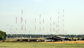
Curtain arrays are a class of large multielement directional radio transmitting wire antennas, used in the shortwave radio bands. They are a type of reflective array antenna, consisting of multiple wire dipole antennas, suspended in a vertical plane, often in front of a "curtain" reflector made of a flat vertical screen of many long parallel wires. These are suspended by support wires strung between pairs of tall steel towers, up to 90 m high. They are used for long-distance skywave transmission; they transmit a beam of radio waves at a shallow angle into the sky just above the horizon, which is reflected by the ionosphere back to Earth beyond the horizon. Curtain antennas are mostly used by international short wave radio stations to broadcast to large areas at transcontinental distances.

The G5RV antenna is a dipole with a symmetric resonant feeder line, which serves as impedance matcher for a 50 Ω coax cable to the transceiver.
In radio systems, many different antenna types are used whose properties are especially crafted for particular applications. Antennas can be classified in various ways. The list below groups together antennas under common operating principles, following the way antennas are classified in many engineering textbooks.

A hexbeam, or hexagonal-beam, is a type of a directional antenna for shortwave, most often used in amateur radio. The name comes from the hexagonal outer shape of the antenna. It may also sometimes be known as a W-antenna, referring to the shape of the driver. The design looks something like an upturned umbrella.
In an antenna array made of multiple conductive elements, a driven element or active element is electrically connected to the receiver or transmitter while a parasitic element is not.
{{cite web}}: CS1 maint: numeric names: authors list (link) — multiple articles and construction reports from Moxon antenna builders. {{cite book}}: CS1 maint: numeric names: authors list (link){{cite web}}: CS1 maint: numeric names: authors list (link){{cite web}}: CS1 maint: numeric names: authors list (link){{cite web}}: CS1 maint: numeric names: authors list (link){{cite web}}: CS1 maint: numeric names: authors list (link){{cite web}}: CS1 maint: numeric names: authors list (link)