Uniflow steam engine

Last updated
Schematic animation of a uniflow steam engine.
The poppet valves are controlled by the rotating camshaft at the top. High pressure steam enters, red, and exhausts, yellow. Uniflow steam engine.gif
Schematic animation of a uniflow steam engine.
The poppet valves are controlled by the rotating camshaft at the top. High pressure steam enters, red, and exhausts, yellow.

The uniflow type of steam engine uses steam that flows in one direction only in each half of the cylinder. Thermal efficiency is increased by having a temperature gradient along the cylinder. Steam always enters at the hot ends of the cylinder and exhausts through ports at the cooler centre. By this means, the relative heating and cooling of the cylinder walls is reduced.

Contents

Design details

Galloway uniflow steam engine, now in Thinktank, Birmingham Science Museum Thinktank Birmingham - object 1956S00658(1).jpg
Galloway uniflow steam engine, now in Thinktank, Birmingham Science Museum

Steam entry is usually controlled by poppet valves (which act similarly to those used in internal combustion engines) that are operated by a camshaft. The inlet valves open to admit steam when minimum expansion volume has been reached at the start of the stroke. For a period of the crank cycle, steam is admitted, and the poppet inlet is then closed, allowing continued expansion of the steam during the stroke, driving the piston. Near the end of the stroke, the piston will uncover a ring of exhaust ports mounted radially around the centre of the cylinder. These ports are connected by a manifold and piping to the condenser, lowering the pressure in the chamber below that of the atmosphere causing rapid exhausting. Continued rotation of the crank moves the piston. From the animation, the features of a uniflow engine can be seen, with a large piston almost half the length of the cylinder, poppet inlet valves at either end, a camshaft (whose motion is derived from that of the driveshaft) and a central ring of exhaust ports.

Advantages

Uniflow engines potentially allow greater expansion in a single cylinder without the relatively cool exhaust steam flowing across the hot end of the working cylinder and steam ports of a conventional "counterflow" steam engine during the exhaust stroke. This condition allows higher thermal efficiency. The exhaust ports are open for only a small fraction of the piston stroke, with the exhaust ports closed just after the piston begins traveling toward the admission end of the cylinder. The steam remaining within the cylinder after the exhaust ports are closed is trapped, and this trapped steam is compressed by the returning piston. This is thermodynamically desirable as it preheats the hot end of the cylinder before the admission of steam. However, the risk of excessive compression often results in small auxiliary exhaust ports being included at the cylinder heads. Such a design is called a semi-uniflow engine

Engines of this type usually have multiple cylinders in an in-line arrangement, and may be single- or double-acting. A particular advantage of this type is that the valves may be operated by the effect of multiple camshafts, and by changing the relative phase of these camshafts, the amount of steam admitted may be increased for high torque at low speed, and may be decreased at cruising speed for economy of operation. Alternatively, designs using a more-complex cam surface allowed the varying of timing by shifting the entire camshaft longitudinally compared to its follower, allowing the admission timing to be varied. (The camshaft could be shifted by mechanical or hydraulic devices.) And, by changing the absolute phase, the engine's direction of rotation may be changed. The uniflow design also maintains a constant temperature gradient through the cylinder, avoiding passing hot and cold steam through the same end of the cylinder.

Disadvantages

In practice, the uniflow engine has a number of operational shortcomings. The large expansion ratio requires a large cylinder volume. To gain the maximum potential work from the engine a high reciprocation rate is required, typically 80% faster than a double-acting counterflow type engine. This causes the opening times of the inlet valves to be very short, putting great strain on a delicate mechanical part. In order to withstand the huge mechanical forces encountered, engines have to be heavily built and a large flywheel is required to smooth out the variations in torque as the steam pressure rapidly rises and falls in the cylinder. Because there is a thermal gradient across the cylinder, the metal of the wall expands to different extents. This requires the cylinder bore to be machined wider in the cool center than at the hot ends. If the cylinder is not heated correctly, or if water enters, the delicate balance can be upset causing seizure mid-stroke or, potentially, destruction.

History

The uniflow engine was first used in Britain in 1827 by Jacob Perkins and was patented in 1885 by Leonard Jennett Todd. It was popularised by German engineer Johann Stumpf in 1909, with the first commercial stationary engine produced a year previously in 1908.

Steam locomotives

The uniflow principle was mainly used for industrial power generation, but was also tried in a few railway locomotives in England, such as the North Eastern Railway uniflow locomotives No.825 of 1913, and No.2212 of 1918, [1] and the Midland Railway Paget locomotive. Experiments were also made in France, [2] Germany, the United States and Russia. [1] In no case were the results encouraging enough for further development to be undertaken.

Steam wagons

A restored 1918 Atkinson Uniflow steam wagon, photographed in 1977 1918 Atkinson, on display, 1977 (01).jpg
A restored 1918 Atkinson Uniflow steam wagon, photographed in 1977

The first large-scale utilization of a Uniflow engine was in Atkinson steam wagons, in 1918. [3] Only one such steam wagon is known to be still in existence; it was built in 1918, spent its working life and a period of dereliction in Australia, and was then repatriated to England and restored by Tom Varley in 1976-77. [4] [5]

Skinner Unaflow

The final commercial evolution of the uniflow engine occurred in the United States during the late 1930s and 1940s by the Skinner Engine Company with the development of the Compound Unaflow Marine Steam Engine. [1] This engine operates in a steeple compound configuration and provides efficiencies approaching contemporary diesels. Many car ferries on the Great Lakes were so equipped, one of which is still operating, SS Badger of 1952. The Casablanca-class escort carrier, the most prolific aircraft carrier design in history, used two 5-cylinder Skinner Unaflow engines, but these were not steeple compounds. A non-compound Skinner Uniflow remained in service until 2013 in the Great Lakes cement carrier SS St. Marys Challenger, installed when the vessel was re-powered in 1950.

In small sizes (less than about 1,000 hp (750 kW)), reciprocating steam engines are much more efficient than steam turbines. White Cliffs Solar Power Station used a three-cylinder uniflow engine with "Bash"-type admission valves to generate about 25 kW electrical output.

Home-made conversions of two-stroke engines

The single-acting uniflow steam engine configuration closely resembles that of a two-stroke internal combustion engine, and it is possible to convert a two-stroke engine to a uniflow steam engine by feeding the cylinder with steam via a "bash valve" fitted in place of the spark plug. [6] As the rising piston nears the top of its stroke, it knocks open the bash valve to admit a pulse of steam. The valve closes automatically as the piston descends, and the steam is exhausted through the existing cylinder porting. The inertia of the flywheel then carries the piston back to the top of its stroke against the compression, as it does in the original form of the engine. Also like the original, the conversion is not self-starting and must be turned over by an external power source to start. An example of such a conversion is the steam-powered moped, which is started by pedalling. [7]

See also

Related Research Articles

<span class="mw-page-title-main">Steam engine</span> Engine that uses steam to perform mechanical work

A steam engine is a heat engine that performs mechanical work using steam as its working fluid. The steam engine uses the force produced by steam pressure to push a piston back and forth inside a cylinder. This pushing force can be transformed, by a connecting rod and crank, into rotational force for work. The term "steam engine" is generally applied only to reciprocating engines as just described, not to the steam turbine. Steam engines are external combustion engines, where the working fluid is separated from the combustion products. The ideal thermodynamic cycle used to analyze this process is called the Rankine cycle. In general usage, the term steam engine can refer to either complete steam plants, such as railway steam locomotives and portable engines, or may refer to the piston or turbine machinery alone, as in the beam engine and stationary steam engine.

<span class="mw-page-title-main">Two-stroke engine</span> Internal combustion engine type

A two-strokeengine is a type of internal combustion engine that completes a power cycle with two strokes of the piston during one power cycle, this power cycle being completed in one revolution of the crankshaft. A four-stroke engine requires four strokes of the piston to complete a power cycle during two crankshaft revolutions. In a two-stroke engine, the end of the combustion stroke and the beginning of the compression stroke happen simultaneously, with the intake and exhaust functions occurring at the same time.

<span class="mw-page-title-main">Poppet valve</span> Type of valve

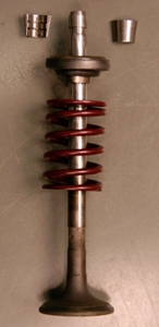
A poppet valve is a valve typically used to control the timing and quantity of gas or vapor flow into or out of an engine, but with many other applications.

<span class="mw-page-title-main">Camshaft</span> Mechanical component that converts rotational motion to reciprocal motion

A camshaft is a shaft that contains a row of pointed cams, in order to convert rotational motion to reciprocating motion. Camshafts are used in piston engines, mechanically controlled ignition systems and early electric motor speed controllers.

<span class="mw-page-title-main">Napier Deltic</span> Opposed-piston engine used in marine, firefighting and BR locomotive applications

The Napier Deltic engine is a British opposed-piston valveless, supercharged uniflow scavenged, two-stroke diesel engine used in marine and locomotive applications, designed and produced by D. Napier & Son. Unusually, the cylinders were disposed in a three-bank triangle, with a crankshaft at each corner of the triangle.

<span class="mw-page-title-main">Valve gear</span> Mechanism for controlling steam flow in a reciprocating steam engine.

The valve gear of a steam engine is the mechanism that operates the inlet and exhaust valves to admit steam into the cylinder and allow exhaust steam to escape, respectively, at the correct points in the cycle. It can also serve as a reversing gear. It is sometimes referred to as the "motion".

<span class="mw-page-title-main">Variable valve timing</span> Process of altering the timing of a valve lift event

Variable valve timing (VVT) is the process of altering the timing of a valve lift event in an internal combustion engine, and is often used to improve performance, fuel economy or emissions. It is increasingly being used in combination with variable valve lift systems. There are many ways in which this can be achieved, ranging from mechanical devices to electro-hydraulic and camless systems. Increasingly strict emissions regulations are causing many automotive manufacturers to use VVT systems.

<span class="mw-page-title-main">Walschaerts valve gear</span> Type of valve gear

The Walschaerts valve gear is a type of valve gear used to regulate the flow of steam to the pistons in steam locomotives, invented by Belgian railway engineer Egide Walschaerts in 1844. The gear is sometimes named without the final "s", since it was incorrectly patented under that name. It was extensively used in steam locomotives from the late 19th century until the end of the steam era.

In a piston engine, the valve timing is the precise timing of the opening and closing of the valves. In an internal combustion engine those are usually poppet valves and in a steam engine they are usually slide valves or piston valves.

<span class="mw-page-title-main">Corliss steam engine</span> Type of steam engine using rotary steam valves

A Corliss steam engine is a steam engine, fitted with rotary valves and with variable valve timing patented in 1849, invented by and named after the US engineer George Henry Corliss of Providence, Rhode Island.

<span class="mw-page-title-main">Johann Stumpf (engineer)</span>

Johann Stumpf of the Charlottenburg Technical College in Berlin is best known for popularising the uniflow steam engine, in the years around 1909, and his name has always been associated with it. The basic uniflow principle had been invented many years before.

<span class="mw-page-title-main">Scavenging (engine)</span> Process used in internal combustion engines

Scavenging is the process of replacing the exhaust gas in a cylinder of an internal combustion engine with the fresh air/fuel mixture for the next cycle. If scavenging is incomplete, the remaining exhaust gases can cause improper combustion for the next cycle, leading to reduced power output.

<span class="mw-page-title-main">Piston valve (steam engine)</span> Form of valve within a steam engine or locomotive

Piston valves are one form of valve used to control the flow of steam within a steam engine or locomotive. They control the admission of steam into the cylinders and its subsequent exhausting, enabling a locomotive to move under its own power. The valve consists of two piston heads on a common spindle moving inside a steam chest, which is essentially a mini-cylinder located either above or below the main cylinders of the locomotive.

<span class="mw-page-title-main">Two-stroke diesel engine</span> Engine type

A two-stroke diesel engine is a diesel engine that uses compression ignition in a two-stroke combustion cycle. It was invented by Hugo Güldner in 1899.

<span class="mw-page-title-main">Expansion valve (steam engine)</span>

An expansion valve is a device in steam engine valve gear that improves engine efficiency. It operates by closing off the supply of steam early, before the piston has travelled through its full stroke. This cut-off allows the steam to then expand within the cylinder. This expanding steam is still sufficient to drive the piston, even though its pressure decreases as it expands. As less steam is supplied in the shorter time for which the valve is open, use of the expansion valve reduces the steam consumed and thus the fuel required. The engine may deliver two-thirds of the work, for only one-third of the steam.

<span class="mw-page-title-main">Tuned exhaust</span> Optimisation of exhaust system geometry

In an internal combustion engine, the geometry of the exhaust system can be optimised ("tuned") to maximise the power output of the engine. Tuned exhausts are designed so that reflected pressure waves arrive at the exhaust port at a particular time in the combustion cycle.

A bash valve is a valve within a piston engine, used to control the admission of the working fluid. They are directly actuated valves, operated by contact between the piston and the valve tip.

<span class="mw-page-title-main">Internal combustion engine</span> Engine in which the combustion of a fuel occurs with an oxidizer in a combustion chamber

An internal combustion engine is a heat engine in which the combustion of a fuel occurs with an oxidizer in a combustion chamber that is an integral part of the working fluid flow circuit. In an internal combustion engine, the expansion of the high-temperature and high-pressure gases produced by combustion applies direct force to some component of the engine. The force is typically applied to pistons, turbine blades, a rotor, or a nozzle. This force moves the component over a distance, transforming chemical energy into kinetic energy which is used to propel, move or power whatever the engine is attached to.

<span class="mw-page-title-main">Willans engine</span>

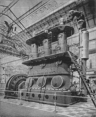
The Willans engine or central valve engine was a high-speed stationary steam engine used mainly for electricity generation around the start of the 20th century.

A uniflow engine is a piston engine where gas flow through the cylinder proceeds in a single unidirectional flow, without reversals between strokes. This gives thermodynamic advantages as each group of ports can stabilise at an equilibrium temperature, rather than being alternately heated and cooled. For internal combustion engines, scavenging is also improved by this consistent flow direction.

References

  1. 1 2 3 The Museum of Retro Technology – Uniflow Steam Locomotives.
  2. "Haute Pression! French High-Pressure Locomotives". 2006-01-03. Retrieved 2019-10-21.
  3. Commercial Motor. 1918-08-15.
  4. Boddy, Bill (June 1977). "V-E-V Odds & Ends The Riley Register's". Motor Sport . p. 676. Retrieved 8 January 2023.
  5. "BBC North West Regional News Material 1973-1986: Programme Details - Further details for Look North West: Friday 22/4/1977". North West Film Archive . Retrieved 8 January 2023.
  6. Bash Valve - description
  7. Steam-powered moped

Sources