The Yarrow boiler design is characteristic of the three-drum boiler: two banks of straight water-tubes are arranged in a triangular row with a single furnace between them. A single steam drum is mounted at the top between them, with smaller water drums at the base of each bank. Circulation, both upwards and downwards, occurs within this same tube bank. The Yarrow's distinctive features were the use of straight tubes and also circulation in both directions taking place within the tube bank, rather than using external downcomers.[1][2][3]
Early watertube boilers
Early use of the water-tube boiler within the Royal Navy was controversial at times, giving rise to the 'Battle of the Boilers' around 1900.[4] These first boilers, such as the Belleville and Niclausse, were large-tube designs, with simple straight tubes of around 4" diameter, at a shallow angle to the horizontal.[5] These tubes were jointed into cast iron headers and gave much trouble with leakage at these joints. At the time, an assumption was that thermal expansion in these straight tubes was straining the joints. These boilers were also large, and although fitted to many pre-dreadnought battleships, could not be fitted to the small torpedo boats and the early destroyers then under very active development.
To provide a lighter boiler for smaller vessels, the 'Express' types were developed. These used smaller water-tubes of around 2" diameter, giving a greater ratio of heating area to volume (and weight). Most of these were of the three-drum pattern, particularly of the Du Temple and Normand designs.[5] This gave a more vertical arrangement of the water-tubes, thus encouraging thermosyphon circulation in these narrow tubes. The previous problems of tube expansion were still a theoretical concern and so the tubes were either curved, or even convoluted into hairpins and S shapes, so as to increase heating area. In practice these shapes gave rise to two more practical problems: difficulty in cleaning the tubes and also difficulty in forming a reliable joint into the water drums, particularly where tubes entered the drum at a variety of angles.
Yarrow's water-tube boiler
Alfred Yarrow developed his boiler as a response to others that had already developed water-tube boilers. This was a long process based on theoretical experiment rather than evolution of practical boilers. Work began in 1877 and the first commercial boiler was not supplied until 10 years later, a torpedo boat of 1887.[6]
Despite this long gestation, the boiler's origins appear to have been most direct. Yarrow's initial conversation with William Crush, head of the boiler department, is recorded to have included a rather direct approach and Yarrow's statements, "We must wake-up about water-tube boilers", "Why not a boiler like this?" (placing his fingers together as if praying), and "Straight tubes?" already expressed two of the boiler's three basic design principles.[6]
Straight tubes
Early water-tube designers had been concerned with the expansion of the boiler's tubes when heated. Efforts were made to permit them to expand freely, particularly so that those closest to the furnace might expand relatively more than those further away. Typically this was done by arranging the tubes in large looping curves, as for the Thornycroft boiler. These had difficulties in manufacturing and required support in use.
Yarrow recognised that the temperature of a water-filled tube was held relatively low and was consistent amongst them, provided that they remained full of water and boiling was not allowed to occur within the tubes themselves. High temperatures and variations only arose when tubes became steam filled, which also disrupted circulation.
His conclusion was thus that straight water-tubes were acceptable, and had obvious advantages for manufacture and cleaning in service.[6]
Obtaining tubes capable of withstanding the increasing boiler pressures was difficult and most makers had already experienced problems with the welds in the tubes. A less obvious benefit of straight tubes was that they could make use of the newly developed seamless-drawn tubes now being produced for bicycle manufacture.[6]
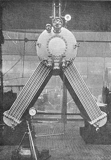
Yarrow's circulation experiments
Yarrow's U-tube circulation experimentCleaning a Yarrow boiler
It was already recognised that a water-tube boiler relied on a continuous flow through the water-tubes, and that this must be by a thermosyphon effect rather than impractically requiring a pump.
The heated water-tubes were a large number of small diameter tubes mounted between large drums: the water drums below and steam drums above. Fairbairn's studies had already showed the importance of tube diameter and how small diameter tubes could easily withstand far higher pressures than large diameters. The drums could withstand the pressure by virtue of their robust construction. Manholes fitted to them allowed regular internal inspection.
The assumption was that flow through the water-tubes would be upwards, owing to their heating by the furnace, and that the counterbalancing downward flow would require external unheated downcomers. In most water-tube designs these were a few large-diameter external pipes from the steam drum to the water drum. These large-diameter pipes were thus a problem for reliability owing to their rigidity and the forces upon them.
Alfred Yarrow conducted a famous experiment where he disproved this assumption.[7][8] Sources are unclear as to whether he discovered this during the experiment, or conducted the experiment merely to demonstrate a theory that he already held.
A vertical U-shaped tube was arranged so that it could be heated by a series of Bunsen burners on each side. A simple flow meter indicated the direction and approximate strength of any flow through the tank at the top linking the two arms of the U.
When only one side of the U was heated, there was the expected upward flow of heated water in that arm of the tube.
When heat was also applied to the unheated arm, conventional theory predicted that the circulatory flow would slow or stop completely. In practice, the flow actually increased. Provided that there was some asymmetry to the heating, Yarrow's experiment showed that circulation could continue and heating of the cooler downcomer could even increase this flow.
Yarrow then repeated the experiment, first with the U-tube at a shallow angle to the horizontal, finally with the entire system under pressure.[7] The results were the same and circulation was maintained.
The Yarrow boiler could thus dispense with separate external downcomers. Flow was entirely within the heated watertubes, upwards within those closest to the furnace and downwards through those in the outer rows of the bank.
Description
End half-section of a boiler, showing the enclosing furnace and flue
Yarrow's production boiler had a simple and distinctive design that remained broadly unchanged afterwards. Three drums were arranged in a triangular formation: a single large steam drum at the top and two smaller water drums below. They were linked by straight watertubes in a multi-row bank to each water drum.
The furnace was placed in the space between the tube banks. Early boilers were manually coal fired, later oil fired. The boiler was enclosed in a sealed casing of steel, lined with firebricks. Brick-lined end walls to this casing housed the firedoors or oil burner quarls, but had no heating surface. The uptake flue from the boiler was in the centre top of the casing, the exhaust gases passing around the steam drum. To reduce corrosion from flue gases over the drum, it was sometimes wrapped in a simple deflector shroud. Usually the lower part of the water drums were exposed outside the casing, but only the ends of the steam drum emerged. The water level was at around one-third of the steam drum diameter, enough to cover the ends of the submerged water-tubes.
The weight of the boiler rested on the water drums, and thus on supports from the firing flat's deck. The steam drum was only supported by the watertubes and was allowed to move freely, with thermal expansion. If superheated, the superheater elements were hung from this drum. Compared to the earlier Scotch and locomotive boilers, water-tube boilers with their reduced water volumes were considered lightweight and didn't require extensive supports.
Later evolution in design
Water drums
Early Yarrow boiler, showing the D-shaped water troughs
The first Yarrow water drums or "troughs" were D-shaped with a flat tubeplate, so as to provide an easy mounting for the tubes. The tubeplate was bolted to the trough and could be dismantled for maintenance and tube cleaning.
This D shape is not ideal for a pressure drum though, as pressure will tend to distort it into a more circular section. Experience of boiler explosions had shown that sharp internal corners inside boilers were also prone to erosion by grooving.
Later boilers used a more rounded section, despite the difficulty of inserting and sealing the tube ends when they were no longer perpendicular. These later drums had a manhole in the ends for access.
Downcomers
The circulation in a Yarrow boiler depended on a temperature difference between the inner and outer tube rows of a bank, and particularly upon the rates of boiling. Whilst this is easy to maintain at low powers, a higher pressure Yarrow boiler will tend to have less temperature difference and thus will have less effective circulation.[2] This effect can be counteracted by providing external downcomers, outside the heated flue area.
Although most Yarrow boilers did not require downcomers, some were fitted with them.[9]
Double-ended boilers
The first double-ended boiler was built in 1905 for the Spanish government. The design was already well-suited to being fired from both ends and it was discovered that double-ended boilers were slightly more efficient in use.
Yarrow's shipyard was always restricted in the size of ships that it could build. Many of their boilers were intended for larger warships and Yarrow supplied these as components to the building yards with larger slipways.
Superheaters
Asymmetric 'double-flow' Yarrow boiler, with superheater
Early Yarrow boilers were not superheated, but with the introduction of steam turbines, there was a demand for increasingly higher steam temperatures.
Asymmetric boilers
The Yarrow superheater consisted of hairpin tubes, parallel to the existing steam generator tubes. One bank of the generator tubes was separated in two, with individual lower water drums for them. The superheater was placed in the gap formed between these, with both ends of its tubes connected to a single superheater header drum, and an internal baffle to separate wet and dry steam.[10]
A secondary effect of the superheater was to increase the temperature differential between inner and outer tubes of the bank, thus encouraging circulation. The two water drums were often linked by unheated downcomers, to allow this flow between the drums. This effect was later encouraged in the Admiralty boiler, where the tubes of a bank were curved apart to leave space for a superheater, whilst retaining the single water drum.
Controlled flow
Only a single superheater was ever installed, on just one side of the boiler. The simplest, and smallest, boilers moved their exhaust flue to this side, passing all of the exhaust through the bank with the superheater. The now-asymmetric boiler could pass all of its exhaust gas through the superheated side as the single flow type.[10] The other bank remained in use for purely radiative heating, often with fewer rows of tubes.
Alternatively the 'double flow' boiler retained full gas flow through both sides, although only one of these contained a superheater. A controllable baffle on the non-superheated side could be closed to increase flow through the superheater.[10] These boilers usually incorporated additional feedwater heaters in the updraught above these baffles.[10]
This was broadly similar to later, high-pressure and oil-fired, versions of the Yarrow. The waterdrums were cylindrical and downcomers were sometimes, but not always, used. The only major difference was in the tube banks. Rather than straight tubes, each tube was mostly straight, but cranked towards their ends. These were installed in two groups within the bank, so that they formed a gap between them within the bank. Superheaters were placed inside this gap. The advantage of placing the superheaters here was that they increased the temperature differential between the inner and outer tubes of the bank, thus encouraging circulation.
The first Yarrow boilers were intended for small destroyers and filled the entire width of the hull. In the early classes, three boilers were used arranged in tandem, each with a separate funnel. The later sets supplied for capital ships used multiple boilers and these were often grouped into sets of three, sharing an uptake.
Land-based boilers
In 1922, Harold Yarrow decided to exploit the increasing boom for electricity generation as a market for Yarrows to build land-based boilers. [14] The first boilers, at Dunston Power Station and Brighton, were of the same marine pattern. As for their naval success, they were recognised for having a large radiant heating area and being quick to raise steam.
Large land-based turbines required high efficiency and increased superheat, so the marine pattern was revised to the distinctive land-based Yarrow boiler. This became asymmetrical. One wing was enlarged and received most of the gas flow. The inner tube banks remained and received radiant heat from the furnace, but the gases then flowed through one of them, over a superheater bank, then through an additional third bank to increase the heat extracted.
Working pressures also increased. From a working pressure of 575psi in 1927, by 1929 an experimental boiler was operated at 1,200psi.[14]
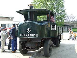
Only one "Yarrow" boiler was used in a railway locomotive, Nigel Gresley's experimental Engine 10000 of 1924 for the LNER company.[15] Having observed the benefits of higher pressures and compound engines in marine practice, Gresley was keen to experiment with this approach in a railway locomotive. As with the land-based boilers, Harold Yarrow was keen to expand the market for Yarrow's boiler.
The boiler was not the usual Yarrow design. In operation, particularly its circulation paths, the boiler had more in common with other three-drum designs such as the Woolnough. It has also been described as an evolution of the Brotan-Deffner water-tube firebox, with the firebox extended to become the entire boiler.
Related Research Articles
A boiler is a closed vessel in which fluid is heated. The fluid does not necessarily boil. The heated or vaporized fluid exits the boiler for use in various processes or heating applications, including water heating, central heating, boiler-based power generation, cooking, and sanitation.
Superheated steam is steam at a temperature higher than its vaporization point at the absolute pressure where the temperature is measured.
A fire-tube boiler is a type of boiler invented in 1828 by Mark Seguin, in which hot gases pass from a fire through one or more tubes running through a sealed container of water. The heat of the gases is transferred through the walls of the tubes by thermal conduction, heating the water and ultimately creating steam.
A high pressure watertube boiler is a type of boiler in which water circulates in tubes heated externally by fire. Fuel is burned inside the furnace, creating hot gas which boils water in the steam-generating tubes. In smaller boilers, additional generating tubes are separate in the furnace, while larger utility boilers rely on the water-filled tubes that make up the walls of the furnace to generate steam.
A superheater is a device used to convert saturated steam or wet steam into superheated steam or dry steam. Superheated steam is used in steam turbines for electricity generation, in some steam engines, and in processes such as steam reforming. There are three types of superheaters: radiant, convection, and separately fired. A superheater can vary in size from a few tens of feet to several hundred feet.
A thermal power station is a type of power station in which heat energy is converted to electrical energy. In a steam-generating cycle heat is used to boil water in a large pressure vessel to produce high-pressure steam, which drives a steam turbine connected to an electrical generator. The low-pressure exhaust from the turbine enters a steam condenser where it is cooled to produce hot condensate which is recycled to the heating process to generate more high pressure steam. This is known as a Rankine cycle.
A steam drum is a standard feature of a water-tube boiler. It is a reservoir of water/steam at the top end of the water tubes. The drum stores the steam generated in the water tubes and acts as a phase-separator for the steam/water mixture. The difference in densities between hot and cold water helps in the accumulation of the "hotter"-water/and saturated-steam into the steam-drum.
A boiler or steam generator is a device used to create steam by applying heat energy to water. Although the definitions are somewhat flexible, it can be said that older steam generators were commonly termed boilers and worked at low to medium pressure but, at pressures above this, it is more usual to speak of a steam generator.
A shell or flued boiler is an early and relatively simple form of boiler used to make steam, usually for the purpose of driving a steam engine. The design marked a transitional stage in boiler development, between the early haystack boilers and the later multi-tube fire-tube boilers. A flued boiler is characterized by a large cylindrical boiler shell forming a tank of water, traversed by one or more large flues containing the furnace. These boilers appeared around the start of the 19th century and some forms remain in service today. Although mostly used for static steam plants, some were used in early steam vehicles, railway locomotives and ships.
A vertical boiler with horizontal fire-tubes is a type of small vertical boiler, used to generate steam for small machinery. It is characterised by having many narrow fire-tubes, running horizontally.
The Stirling boiler is an early form of water-tube boiler, used to generate steam in large land-based stationary plants. Although widely used around 1900, it has now fallen from favour and is rarely seen.
Boilers for generating steam or hot water have been designed in countless shapes, sizes and configurations. An extensive terminology has evolved to describe their common features. This glossary provides definitions for these terms.
The Sentinel boiler was a design of vertical boiler, fitted to the numerous steam wagons built by the Sentinel Waggon Works.
Three-drum boilers are a class of water-tube boiler used to generate steam, typically to power ships. They are compact and of high evaporative power, factors that encourage this use. Other boiler designs may be more efficient, although bulkier, and so the three-drum pattern was rare as a land-based stationary boiler.
Spiral water-tube boilers are a family of vertical water-tube boilers. Their steam generating tubes are narrow spiral tubes, arranged in circular fashion around a central vertical water drum.
A high-pressure steam locomotive is a steam locomotive with a boiler that operates at pressures well above what would be considered normal for other locomotives. Most locomotives operate with a steam pressure of 200 to 300 psi. In the later years of steam, boiler pressures were typically 200 to 250 psi. High-pressure locomotives can be considered to start at 350 psi (2.41 MPa), when special construction techniques become necessary, but some had boilers that operated at over 1,500 psi (10.34 MPa).
The Johnson boiler is a water-tube boiler used for ship propulsion.
A steam generator is a form of low water-content boiler, similar to a flash steam boiler. The usual construction is as a spiral coil of water-tube, arranged as a single, or monotube, coil. Circulation is once-through and pumped under pressure, as a forced-circulation boiler. The narrow-tube construction, without any large-diameter drums or tanks, means that they are safe from the effects of explosion, even if worked at high pressures. The pump flowrate is adjustable, according to the quantity of steam required at that time. The burner output is throttled to maintain a constant working temperature. The burner output required varies according to the quantity of water being evaporated: this can be either adjusted by open-loop control according to the pump throughput, or by a closed-loop control to maintain the measured temperature.
A thimble tube boiler is a form of steam boiler, usually provided as an auxiliary boiler or heat-recovery boiler. They are vertical in orientation and would be considered a form of water-tube boiler.
The Fairbairn-Beeley boiler was a design of fire-tube stationary boiler developed in the late 19th century. It takes its name from its two developers, Sir William Fairbairn and Thomas Beeley
References
Wikimedia Commons has media related to Yarrow boiler.
↑ Kennedy, Rankin (1912). The Book of Modern Engines and Power Generators. Vol.VI. London: Caxton.
1 2 Milton, J. H. (1961) [1953]. Marine Steam Boilers (2nded.). Newnes.
↑ Borthwick, Alastair (1965). Yarrows: the first hundred years. Yarrows.
↑ Rippon, Cmdr. PM (1988). The evolution of engineering in the Royal Navy. Vol.1: 1827-1939. Spellmount. pp.50, 76–77. ISBN0-946771-55-3.
↑ Nock, O.S. (1966). "9: Unconventional Locomotives 1929-1935". The British Steam Railway Locomotive. Vol.II, from 1925 to 1965. Ian Allan. pp.106–109.
This page is based on this Wikipedia article Text is available under the CC BY-SA 4.0 license; additional terms may apply. Images, videos and audio are available under their respective licenses.